Archive
Mini blog – plant tracking and machine control
ON Tuesday I was called in to a meeting with the project director and Carillion’s head of “Survey and Drone research” – sounds cool but it’s definitely not. Apparently my experience of GPS within the military was my golden ticket in to this little shin-dig.
With regards to an exclusion zone on this site, the PD is keen to ensure that all plant be monitored and prevented from accessing areas they could cause damage to the tunnels below.
The suggested solution is to use the same GPS monitoring that is used on plant during road construction. A system that can control the plant as well as give feedback as to the position and angle of the blade etc. This is a brilliant system, but I fear it may be overkill and it is tres expensive (£30k per system plus £10k for a box on the roof to correct all the GPS readings). Rental prices are available, but for a 2 year programme, purchasing may be the way to go.
The actual customer requirements are:
- Warn operators when they are approaching an exclusion zone
- Ability to identify location of plant to confirm if issues in tunnel are plant related
- Maintain a record of locations for legal purposes (arse covering)
Problems:
- Demolition area is an exclusion zone to all non-essential personnel – ie operators only
- Physical barriers are likely to get covered in arisings or crushed any way
Has anyone experience of anything like this, or are there any suggestions for a different system?
I’ll update with the winning solution!
From Cowboys to City Slickers
-
Phase 2 – Completion of Chaffey RE Wall
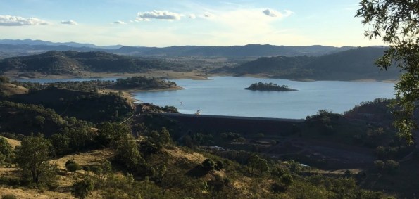
Photo 1 – Southern View of Chaffey Reservoir
In my last week on site at Chaffey Dam I was able to witness the completion of the final layer of soil placement after having laid the very first facing panel seven months earlier. The Chaffey Dam RE Wall was used to increase the crest height of the existing embankment dam to withstand the PMF for the catchment and currently stands 6.9m in height, 7.22m wide and 502m in length. With crest roads works still be complete the final crest height will be 7.2m.
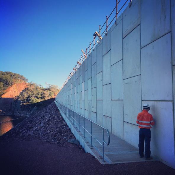
Photo 2 – Upstream Face of Completed RE Wall at Midpoint
-
Crest Works
Prior to my departure the crest works were well under way. Upon completion, the crest was to be used as a service road and so comprise of a bitumen sealed road with combined guard rail/ handrail on the downstream face. On the upstream face, the original 1.7m high pre-cast concrete parapets (or ‘L” panels) were to be installed.
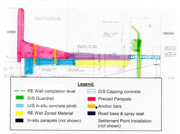
Fig 1 – Typical Crest Section
-
Vibrating Screed Rail
To support the precast “L” units, a 500m concrete plinth (6m x bays) was required. As access was difficult due to the close proximity to the edge of the RE Wall it was proposed that a steel support frame was designed to support the vibrating screed.
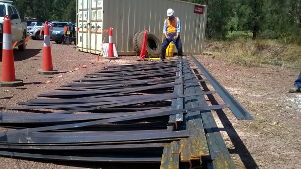
Photo 3 – SPE Having a Moment after Stubbing his Shin on my Screed Rails

Fig 2 – Typical Plinth Section Detail
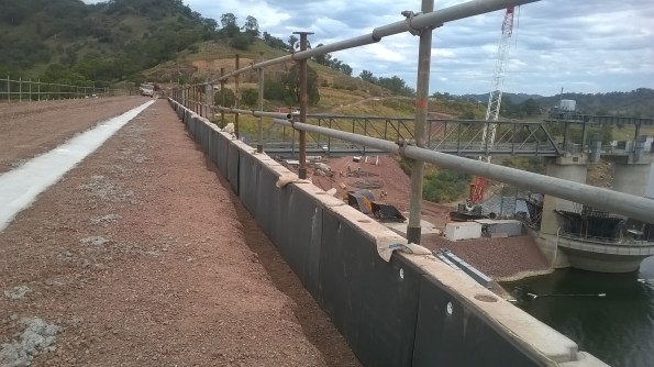
Photo 3 – Proposed Plinth Location
For simplicity, cost saving and time the steel rail concept was pursued. I assisted in the design, procurement and installation of the simple vibrating screed rail. Following review by the SPE and PM the proposal was accepted. Designs were produced and placed to tender across local steel fabricators. Essentially, it was designed to perform as a guide upon which a vibrating screed could be employed whilst also enabling the construction of circular voids within the fibrecrete slab (to allow subsequent HDG steel dowel placement). Geometrically, the simple steel frame was a perfect fit, however the structure was not without fault. The slender steel strips sagged greater than predicted. The strips were simply required to align white PvC conduits vertically, (allowing a circular voids to be created). To counter the bending, the 5mm steel strip could have been either increased in depth in order to reduce the slenderness or even reinforced with an additional steel strip along the axis. Unfortunately, rotating the strips 90 degrees was not an option due to the functional requirement.


-
Fibre Crete

Photo 4 – Example of Fibre Reinforced Concrete
As part of the crest completion works for the Chaffey Dam Augmentation and Safety Upgrade(CDASU) a 500m, concrete plinth (83 x 6m bays) was required to support precast concrete “L” panels on the upstream face of the dam. Due to the unusual geometry of the plinth (see Fig 2), the reinforcement was not straight forward. It was to comprise of 3 individual sections of steel due to limitations in the bending of the steel and logistical constraints. I therefore conducted a comparison between the use of a typical reinforced concrete slab using rebar and Steelfix (Hanson ready-mix fibrecrete). My research concluded that whilst the fibre reinforced concrete will reduce the effects of plastic shrinkage and a negligible increase in the materials tensile strength, it typically should not be considered as an alternative to well placed concrete and reinforcement within structural concrete fibre-crete.
However, for application in question and the relatively low loadings, fibrecrete was deemed suitable. In addition to the structural properties, it was assessed to to better value for money as construction time was significantly reduced and crucially, it did not required the high logistical costs associated with several tonnes of pre-bent steel reinforcement.
-
Countering the Effects of Differential Settlement
The deliberate variation in RLs between the surface of the crest at the centre and the dam and the abutments was approximately 250mm upon completion. The raised central portion was designed to allow for the differential settlement expected. As a clay core embankment dam is constructed, the partially saturated soil is compacted and consolidates as the water is expelled. This results in a reduction of volume of the soil mass.
As Chaffey Dam is constructed upon a rock foundation, it is the profile between abutments that will initiate the differential settlement. By this, I mean that the geometry of the void between the two embankments will result in a varied reduction in volume of clay core as you move across the dam (see figures below).
It is the differential settlement that has the potential to initiate lateral cracks within clay core of the embankment dam due to the tension that will develop in the dam crest where the foundation profile differs. At such points where a significant settlement differential exists, hydraulic fractures may result due to the low stress zones created along the surfaces (see fig below). Consequently, uncontrolled water flow may occur between the upstream to downstream of the structure…not ideal in a dam. Fortunately, most embankment dams experience 80 – 90% of the total settlement during the construction. Consequently, the stresses established in the construction phase assist to control the likelihood of low stress zones and cracking.

Differential Settlement initiated by Dam Profile

Differential Settlement initiated by foundation material
-
Leaving Chaffey
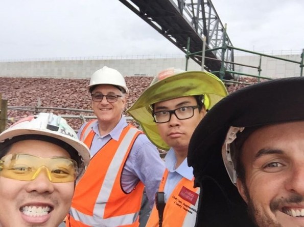
Photo 5 – “Special” Engineers at Chaffey

Photo 6 – Placement of the Final RE Wall Panel
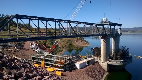
Photo 7 – MGS Construction Feb 2016

Photo 8 – Definitely NOT the Boolarong Frog that Delayed the Project by 5 years…
-
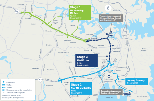
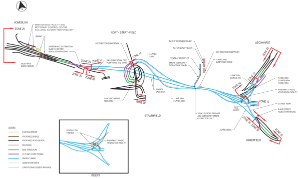
PHASE 3 – WestConnex M4 East Project
For my Phase 3 placement I am working on the WestConnex M4 East Project in Sydney. It is being designed and constructed by the CPB Samsung John Holland Joint Venture (CSJH JV). The M4 East Project will comprise of two new, three lane carriageways of which 5.5km runs below the city. Several access sites are to be installed along the 5.5km stretch to allow concurrency of works, enabling the removal of earth at multiple points. As such numerous cut and cover structures are to be installed.
My Role – Temporary Works Design Coordinator/ Designer
The schedule for my phase 3 attachment is broken down into three periods. Initially, I will be employed as the Temporary Works Design (TWD) Coordinator before working within a civil design team (AEH), a structural design team and finally a geotechnical design team (PSM). For the TWD Coordination role, my key duties are listed below but essentially the position will offer exposure to project-wide activities, enabling an insight into a broad variety of design packages, the overall design process and interaction with designers and PM’s leading each area of construction. Within each area, numerous works packages are raised which must go through a series of comprehensive design stages prior to release for construction. It is my responsibility to coordinate all aspects within each package, reviewing it at each stage before releasing for both internal and external review.
As I transition to purely conduct design I will focus upon one of the works package which I will have previously initiated as the TWD Coordinator. The proposed works package has been chosen due to the variety of engineering within. Essentially, it is a confined area of brown field site with varying levels which includes a haul road, a settlement pond, a portal frame acoustic shed containing a 7 x 7m vertical shaft and is in close proximity to housing and primary road. Initially, I will be analysing the portal frame and foundations before moving on to the shaft design with the geotechnical team.
Primary Responsibilities
Coordination
- Coordinate the preparation of temporary works design briefs (TWDB’s) with the Project Engineers and Project Managers for the tunnel and civil construction sites.
- Co-ordinate the temporary works design aspects of the traffic staging and surface construction zones.
- Assist in the preparation of Temporary Works Design Reports
- Maintain project wide Temporary Works Register (TWR)
- Brief Temporary Works design consultants on the design activities
- Participate in Safety in Design Reviews (SiDR) for the Permanent and Temporary Works
Design
- Develop a working knowledge of Structural Design Activities under supervision of the Senior Structural Engineer.
- Review design criteria and applicable standards.
- Analyse load cases and perform structural analysis using Microstran
- Perform designs for reinforced concrete and structural steel elements
- Review traffic stages and road geometry
- Review drainage and pavement designs
- Train in the use of Strand 7 and RAPT software
Life in Sydney!
Relocating from Tamworth was a pain.. Yet despite my initial reservations about leaving the country life for city, it is pretty awesome here. Cycling over the Harbour Bridge each morning makes up for any problems faced throughout the day.
Webbo Newspaper Article –Beers anyone ?…
Towards the end of my time at Chaffey Dam I had to deliver the quarterly Project Update Brief. The audience included all principle stakeholders, members of the local community, enviro, H&S, council members and the media.. As my PM kindly mentioned the fact that the original Chaffey Dam was built in 1976, also with the assistance of a British Army Officer, Capt RC Morgan, the busy Tamworth media jumped on the historic link and to my delight wrote this article…
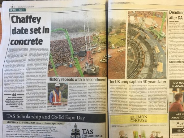
Chaffey Dam Media Article
Is one crane enough?
The Problem
In a skyline full of Tower Cranes (TC) and rapidly rising high end residential and commercial projects, I confidently assumed that the ability to move construction resources around each of the capitals many project sites was a well-managed logistical challenge. Unfortunately, one of the seemingly obvious issues currently causing some contention on my site is the limited availability of heavy lifting equipment. You would think that providing enough lift capacity for a large construction task is a simple thing to get right but as it currently stands, the project has only one TC supporting all construction activities. That comprises a lot of lifting operations; particularly when you consider it includes support to permanent works on three different buildings, temporary works, scaffolding movement, routine site support tasks such as waste removal and welfare setup, concrete placement, unloading of frequent deliveries and support to a MOLA (Museum of London Archaeology) investigation ongoing in one isolated corner. It is clear that almost all work activities on site requires lift support in one capacity or other.
From a project management and commercial perspective this creates an interesting working environment. As a direct result of the apparent shortfall, the subcontractors are now competing for the limited available crane support on a daily basis. In many cases these same contractors are subsequently struggling to achieve progress in line with their own ambitious build schedule because, according to every daily progress summary I have attended so far, the TC is unavailable to move equipment and resources across our very constrained site.
Issue Mitigation
To attempt to mitigate this issue, the principle contractor have temporarily allocated control of TC1 to the sub-contractor completing the essential works on the critical path. As it presently stands that priority lies with the slip form construction of the central concrete shear core in the main tower, currently up to level 2. This core is being constructed in two sections due to its size. For context, each half of the slip form requires approximately 50 crane lifts per day to feed a 50 man gang with all of the steel, formwork and resources required to maintain the scheduled form rise of 1.4m per day. This estimate only includes lifting the resources from the storage area up to the formwork and does not also include unloading upwards of ten lorry deliveries of resources each day. Movement of scaffolding, concrete decking formwork, and the lifting of structural steel frame elements into position are all in competition with the slip form for crane time.
The project management team are also now considering options to reduce the impact of this crane issue on the works programme. These include the installation of a temporary crane (Limited capacity of only 3 Tonnes) in addition to weekend and night works, both of which will increase the overall cost of the works in the short term.
Cost Implications
In numerous situations many of the contractors have brought in labour and resources to complete tasks, only to find that the crane has been allocated in support of other activities. As a result there are frequent occasions where a contractor has workers and resources on site yet is unable to complete scheduled work, at significant cost to both the main contractor and sub-contractor. The resultant effect is that other structural elements and less critical works are now falling weeks behind the original build schedule. This inevitably causes dispute between various sub -contractors which requires careful management and the occasional element of low level dispute resolution.
I suspect this will remain a considerable project management issue until TC2 and TC3, self-climbing cranes suspended from the main shear core, are installed once it reaches floor 10. In the long term it also has potentially significant contractual and commercial implications. Brookfield Multiplex almost exclusively use sub-contractors for all construction aspects on their projects. The only element that they seem to provide themselves is the provision of the Tower Cranes. When the sub-contractors designed their own programme and tendered for the works package they considered availability of lift in accordance with the main contractors lifting plan.
Who is to Blame?
As you would expect on a project of this scale (£460m), identifying and apportioning responsibility for the issue is an ongoing priority. On this project there appears to be an underlying discrepancy regarding the understanding of crane availability during the early stages of project procurement. The Project Managers (PM) formal position is that all the sub-contractors were informed that there would only be TC1 on site at this stage of the project. He is therefore of the view that they costed and programmed the work on that information and therefore responsibility for delays and subsequent costs lie solely with each sub-contractor. The sub-contractors by comparison have stated that during the initial tender process they were told there would be a second TC available by this stage, effectively placing responsibility for delays at the door of the main contractor.
Though all parties on site are working hard and compromising for the benefit of this project, it will be interesting to see where overall responsibility for delay costs fall should elements of work continue to fall behind schedule. As a result, the sub-contractors complain regularly about the lack of crane time (every meeting), I assume to record the issue from their perspective before it leads to an expensive compensation claim further down the line. Likewise, the project management team appear to be strengthening their own position on this issue to allow easy apportion of responsibility elsewhere in order to protect the interests of their own profit margin.At the moment the lack of adequate crane support is not impacting on the critical path, but with weekly site running costs in the region of 300k, further long term delays arising from this simple problem are likely to have expensive consequences into the future.
Grab your Stetson and Run for your life..
Grab your Stetson and run for your lives!!! – BRISBANE CASINO TOWERS

What the client is selling it as.
Introduction. So I started work at Brookfield Multiplex on the Casino Towers project on Hope St in South Brisbane. The project is a 30 storey residential tower block with 6 floors of basement. The contract is a fixed price Design and Build contract for Metro Property Development. BM has taken on all of the risk with this contract under a fixed price and a tight deadline. Time and cost are paramount with tough liquidating damages for overrunning, so the pressure is on. Much of what the project team do is manage other sub-contractors and liaise with their contracted designers. Location wise the site is situated in an interesting area between two blocks of high-rise social housing whose occupants are none to happy about our work and have been keen to let us know by throwing their used needles over their balconies and into our site.
 The clowns to the left of us

The jokers to the right

Stuck in the middle in poo or Acid Sulfate Soil (ASS)
Contract out risk. At the moment we are at excavating the basement. The team has little to no experience of excavating basements and have sub-contracted this phase of a contract to Delta on a Design and Build contract. Delta in turn have sub-contracted the propping system to QPS, with Delta taking on the bulk of the mud moving for themeselves. Unfortunately BM sub-contracted the piling work out to Franki Pile and as the supports and wall work as a system are still carrying much of the can. Wailers are clashing with the future floor slabs and given that the site is at a slight angle, it has all got very complicated.
![Q2454-0001[01] (1)](https://pewpetblog.com/wp-content/uploads/2016/03/q2454-000101-1.jpg?w=595)
Prop Layout at first level of supports the remainder is Ground Anchors
Managing Sub-Contractors. While BM has contracted out the basement they seem to have little leverage into motivating the sub-contractors. They have been accused by the subbies of micromanaging but, it is clear that the subbies are not up to the task. The secant pile wall/propping system has not been designed for construction loads and we can’t even unload stores close to it. On the flip side it would seem that with only one engineer on the project up to this point the scale of the task has over matched him and BM have not asked the right questions before they got to this point.

Struggling to fit the whalers in place
Propping system. QPS are the subbies in charge of the propping system and are more used to ground anchor systems and have struggled with installing a workable propping system. This is the biggest job they have done and frankly it shows. My key criticisms are they insist on welding everything on site, as opposed to preparing off-site and connecting with bolts on site. At the last count 9 of the first 10 welds have failed and need to be redone. They have not really thought about how it will go together and many items have arrivied out of tolerance. The project is now about a month behind schedule. I took a ride out to their fabricating facility. There is a huge capability gap from what we saw at Nu-steel and what QPS can produce. The whole prop system should have gone in last week but the wailing system still hasn’t been fitted. The picture below shows Delta struggling to get the end wailer into place.


The journey of the whaler from factory to floor
H&S. So there are so many issues I scarcely know where to begin. My first appointment was at BM headquarters in the Central Business District. The meeting was about enforcing stricter H&S standards on the various sites around Brisbane. The overarching thing was about moral courage (where have I heard that before) and about safety in design. Monday was a scheduled no work-day so I had the opportunity to inspect the site without any of the sub-contractors (or unions) around. The sub-contractors approach was certainly different from anything I has seen in the UK’s. The stairs into the basement had been undermined by the heavy rains and were pretty rickety. I was also struck by the confined nature of the site and the little separation of people and plant.

Our Union Rep checking H&S standards -integrity is not his strong side. You can see the plunged columns that will support the working platform.
Labour disputes. There have been real issues with unions in Queensland. At the start of the week a construction site on the next street had been shut down after a union walkout. By Tuesday, it was our turn with the union rep/commissar proving his wide and diverse vocabulary regarding his concerns about H&S on site. The union used the rickety stairs and the lack of any other alternative exit to shut down the site and to be fair he had a fair point. However, you can see the reps keen interest in PPE as he encourages the Delta employees to ‘knock off’ for the weekend on Friday.My role – Resitting Exercise Cofferdam, working out how I can get an excavator to move the ASS without exceeding the maximum surcharge of 5 KPa within 3m of the wall.
Boundaries, Properties, Groundwater, Contamination…Constructability!
 .
.
The calm before the storm…
On the 29th February I started work for Expanded Civil Engineering on the redevelopment of the Shell Centre. Expanded are a business group of Laing O’Rourke so all of the employees in the site office are Laing O’Rourke employees but are wearing the Expanded badge.
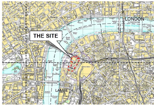
The project is a redevelopment of an existing site which was completed in 1962. The 1962 complex consisted of a high rise tower with a connecting 12 storey reinforced concrete low rise “horse shoe” shaped wing building. The existing structure is a concrete framed building above a podium with two levels of basement below. The site itself is adjacent to the major transport hub of London Waterloo. It is bounded by York Road to the east, Chicheley Street to the south, Jubilee Gardens to the west and the railway viaduct to the north. Running rail tunnels such as Bakerloo and Northern lines run beneath the site.
The redevelopment master plan has a mixture of commercial and residential buildings. The scheme retains the existing Shell Centre tower and site wide basement raft slab and walls with demolitions above and below ground, and with new construction comprising 2 commercial and 6 residential buildings with a two-storey basement in the north and a three-storey basement in the south of the site. It is worth noting that the residential buildings will have no social housing. The government requires up to a third of all new residential buildings to be affordable housing. However the owners have got round this by investing in a local school. It would appear there is far too much money to be made in this central location to waste it on social housing!
Site location
The proposed development will broadly comprise:
- Demolition of the existing site building, with the exception of the Shell Centre Tower
- Extension of the existing basement in the north east corner of the site and around the London Underground Ltd (LUL) ticket office
- Reconfiguration of the LUL ticket hall
- Construction of a new site-wide two-storey basement structure within the confines of the existing basement
- Construction of eight new mixed commercial / retail and residential buildings
Currently separate contractors, McGee, are completing the demolition of the existing buildings. They will demolish all the buildings down to their structural slab level. The site will therefore have multiple starting levels as shown below.
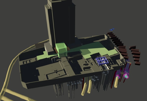
What the site should look like after the demolition works have been completed
The demolition works will be ongoing for a number of months and leads to a very congested site. However, Expanded (and more importantly the client) are keen to get working the moment there is enough space so construction will start in the southern end and follow the demolition works sequentially through the site.
 An example of how congested the site can be; the Expanded piling rig is in the background
There is also a growing concern with the construction plan changing last minute. McGee have proceeded with the demolition quicker than expected and the client therefore wants to accelerate the raft slab construction process. This would involve changing the whole sequence of slab pours and presents additional logistical challenges. The project engineer has so far not changed any plans as he is sure McGee will slow down soon.
An interesting factor has also occurred with a dispute between Expanded and McGee. It has been discovered that the guide wall for a secant pile wall has not been put in the right place by McGee (this has many in the Expanded office scratching their head as no one is sure as to why McGee, the demolition contractor, was tasked with casting a guide wall for Expanded). There is an ongoing dispute as to who is going to pay for it as the site was handed over, although no as-built survey was complete prior to hand over which is why no one has picked this up until just before the pile rig started piling. The dispute is ongoing…
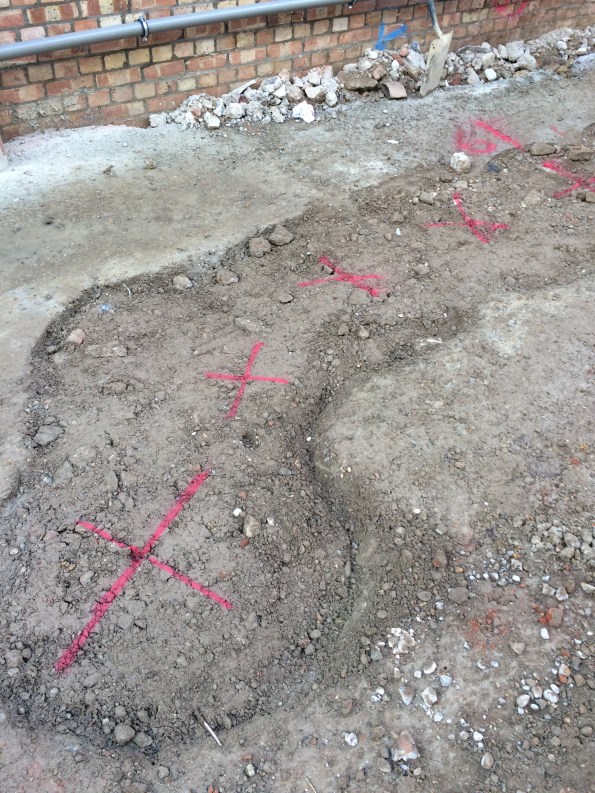
Red crosses show where the center of the piles should be compared to the guide wall
Currently we are in ‘the calm before the storm’; we will not be starting work on the basement raft slab until later this month and there is only minor ground works ongoing for the time being. In the mean time there is a lot of planning and work going on as most of the method statements for the works are yet to be written. This is quite frustrating for me as I find myself (much like phase 1!) writing method statements for processes I have only ever seen on paper. As a result I have to ask for guidance every half an hour! However I will be getting plenty of time on site in about 2 weeks for the foreseeable future.
In other news if anyone on the patch in Kingston fancies a game of squash, Jonny and I play at 1930 on a Wednesday night.
100 Bishopsgate – Understanding The Project
Project Background
On the 23 Feb 16 I started work with Brookfield Multiplex (BM) Construction Europe Ltd on the 100 Bishopsgate Project in central London. The completed project aims to provide approximately 950,000 Sq ft of high quality office and retail accommodation across two buildings, as well as a newly created half-acre public square. In general terms, the project has been broken down into three clear components; the Tower is a 40 story commercial office building which is designed to provide 32 office floors of highly efficient column-free accommodation, each measuring approximately 20,000 ft2. The Podium, which connects into the tower, offers five podium floors of 44,000 square ft each. Two basement levels under both of these structures provides room for services and car parking. 15 St Helens Place is designed as a 7 story steel frame and concrete slab structure which will be tied in to an existing retained stone facade and will feature a restaurant opening onto a public plaza and five office floors of 8,000 ft2 each. The project value is in the region of £460 Million and is scheduled to run for another 3 years.

Fig 1.1 – Plan view of 100 Bishopsgate Project as at 0900 01/03/16
Structural Design
In my first few days the site engineer who was also involved in the full design process of this building kept saying the same two things to me, both of which will be familiar to PET (C) students after phase 1. These were 1) ‘It’s all about stiffness. Stiffness is everything’ and 2) ‘Follow the load path, it’s as simple as that’. I’m not convinced it’s quite that easy, but based on his advice and a vague memory of our lecturers saying something similar in class I thought it wise to spend the first week trying to increase my understanding of the way in which each structural element has been designed to behave, both in the short term temporary condition and in the long term permanent state. In the most basic description I can muster, this is as far as I have got:
Below ground level, two basement floor walls are supported laterally, in the temporary and permanent state, by concrete slabs (GL, BL1 and BL2) acting as permanent propping between a perimeter secant pile wall. Vertically, these slabs are supported by shear connections to steel plunge columns and additional reinforced concrete columns.
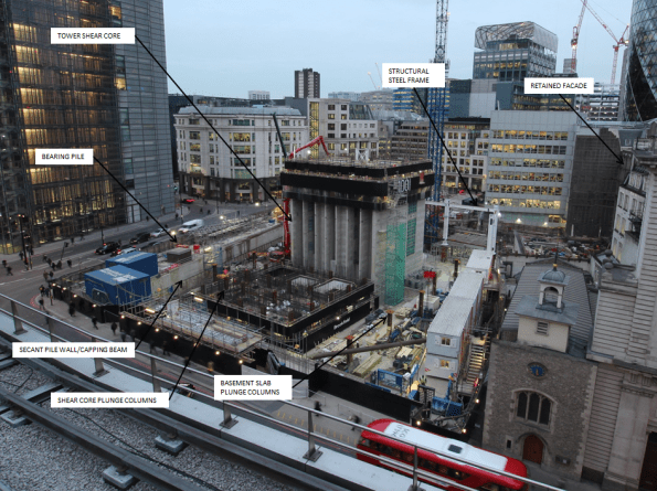
Fig 1.2 – Shear core progress imagery as at 1600 01/03/16
The Tower – Shear Core
Tower 1, as you would expect, is being constructed from a glass clad steel frame and composite concrete deck structure connected to a large central concrete shear core. This shear core, in the permanent state, is designed to carry roughly half of the Towers self-weight vertical load. It also transfers all of the high lateral wind loads (Max load of 32 MN in one pile) to ground through a series of very large reinforced concrete piles (Up to 1800mm dia) positioned directly under the core pile cap. They are therefore designed for the compressive and tensile forces resulting from combinations of self-weight and various wind loading conditions.
The Tower – Steel Frame
In addition to the shear core, the structural steel frame transfers self-weight load through large steel plunge columns located outside the shear core footprint or directly into large concrete piles outside the secant pile perimeter. The plunge columns have been cast into large diameter concrete piles (Up to 2400mm) that run to a depth of approximately 60m below ground level. This plunge column and pile system is designed to carry approximately half of the vertical load of the steel frame tower structure (Max load of 45.4 MN in each column), with the other half transferred down the shear core itself. Though the steel frame and plunge pile system provides additional lateral stability to the concrete core as it increases in height, in both the short term and long term condition all lateral wind loads are designed to be transferred through the core pile cap only.
In certain positions the design uses raked external columns that rise to a height of four floors. In the permanent state the load transferred from the self-weight of the completed tower induces a lateral, outward stress at the base of this column. In order to counteract this stress a large beam at ground floor level has been designed to resist these high temsile loads. The architects design (of course it does!) limits the size of the structural beam available, as a result specialist high tensile steel Gewi Bars have been selected to increase the tensile capacity of the concrete beam without increasing the amount of reinforcement bar required. With a quick google search I found 50mm Gewi Bars that can provide a yield capacity the region of 1MN each. There are 12 bars designed into the concrete beam and as a result are clearly critical beams behaviour in the permanent condition. At the moment there is an issue with resourcing these bars which has the potential to delay the critical path of this project by 7 weeks. This site runs at approximately £300k each week so the prospect of such a delay has got the Project Manager reasonably upset. I’ll cover this issue and my opinion on the project teams inital approach to mitigation in a more detailed subsequent blog.
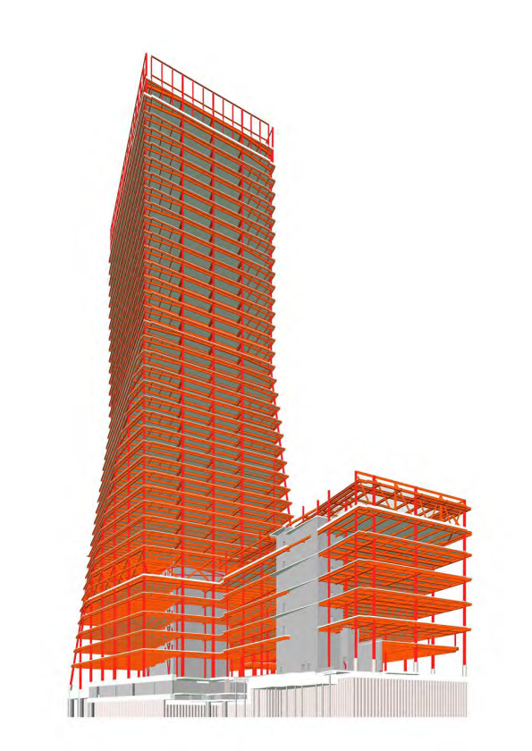
Fig 1.3 – Structural Frame Design
Podium and 15 St Helens Place
The Podium structure contains two smaller concrete shear cores surrounded by the same steel framed system used on the Tower. Over on the 15 St Helens site, a further two concrete shear cores will also be surrounded by a new steel frame and composite concrete deck structure. This new building will tie into an existing stone façade which must be retained in accordance with local conservation regulations. Currently this façade is restrained by a temporary steel frame structure on the front face. Other than self-load, this stone facade will not carry any additional vertical or lateral load imposed by the new steel frame structure emplaced behind it.
The Tower Load Path
The following diagram outlines my first attempt at a load path diagram for the tower component of the structure once complete. You’ll note I have indicated that the lower slabs are in compression from the total horizontal stress caused by the pore water pressure and effective stress behind the secant pile wall. The ground level slab on this diagram represents the position of the beam where the Gewi bars are required to provide increased tensile capacity.
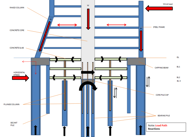
Fig 1.4 – Initial Load Path Analysis
Construction Method in General
The construction method of this project is a reasonably interesting aspect. Where resources allow, work on the three structures is being undertaken concurrently. In very general terms, my current understanding of the build sequence for the Tower component is as follows:
1. Secant Pile Wall and External Bearing Pile Installation
2. Perimeter Capping Beam
3. Internal bearing piles and plunge column installation
4. Excavation to BL1 (Exposing plunge columns)
5. Install Tower Crane 1
6. Commence Shear Core East Slip Form and St Helens Place foundation
8. Shear Core West and East Slip Form to level 6 – Install bracing steel work
9. Construct GL slab (Permanent Prop)
10. Emplace lower level steel frame (Minimum of five floors behind west core level)
11. Continue Shear Core to Level 10
12. Excavate to pile cap level
13. Construct 15 St Helens Place Steel Frame
14. Construct pile cap/BL2 slab (Permanent prop) and connect shear core concrete walls down to pile cap
15. Recommence core build beyond floor 10 and install BL2 concrete columns
16. Construct BL1 slab (permanent prop) and supporting columns
17. Install Tower Crane 2 and Tower Crane 3 (Both self-climbing cranes loaded onto the shear core)
18. Continue to Install structural steel frame for lower floors – Min of 5 floors between slip core and steel level
19. Install concrete decking – Min of 2 clear floors behind steel work
20. Install glass cladding on lower floors – Min of 8 floors below concrete decking
21. E&M fit out – Min of 4 floors behind façade cladding
22. Continue process to top out
This build programme involves top down and bottom up construction at the same time. It is designed to allow the structure on the lower levels to be completed, including fit out, as the building above it continues to rise to the point of top out.
At present state the site is excavated to BL1 and the concrete sub-contractor has started slip forming the west component of the main core. As soon as the Ground floor slab is in place (Gewi bar dependent) excavation of the basement will commence whilst the core continues to rise. Currently, the concrete core (East) up to level 6 is only supported vertically by a series of steel plunge columns that are cast below BL2 into large concrete piles. The bearing capacity of these steel plunge columns is designed for a maximum vertical load when the core is at floor 10, steel work is at floor 5 and concrete decking is at floor 1. Once the structure gets to this position these steel columns will be at the SLS design limit. Therefore construction of the lower basement concrete shear core and connection to the pile cap at BL3 is essential before further floors can be added beyond this point. As a result the progress of the concrete core upwards beyond level 10 (Critical path activity), is completely dependent on the top down construction of the basement levels.
As it stands there are a number of obvious issues which threaten delivery of the project along the critical path, I hope these will make good TMR submissions in the near future and I will try to update on how these are resolved and mitigated as the project team work through them.
CLOUD BREAKING DESIGN – AUSTRALIA 108
‘Australia 108 is a highly sculptural residential tower unlike any other in Australia. Its slender form is highlighted at the Cloud Residences levels by a golden star burst expression and then morphs into a curvaceous profile against the sky. The star burst which contains the resident facilities is inspired by the Commonwealth Star on the Australian flag and is an obvious celebration of the sense of community within the building’ – Fender Katsalidis Architects
This is what it looks like now….

This is what it will look like in 2020…

Project Overview: Australia 108 will be a 319m, 100 story residential building in Melbourne. When complete, it will be the tallest residential building by roof line in the Southern Hemisphere.
It is a design and build, fixed-sum contract to the value of $500m AUS. There is one basement level, one level of retail, 10 podium levels for car parking and the remaining floors to level 100 will be residential and amenities. To note the penthouse has sold for $25m AUS (equivalent to £12.5m) to give an indication of the quality and desirability of this build. Site preliminaries commenced in late May 15 and the foundations in Oct 15. The basement structure is due to finish in Sep 16 when construction of the superstructure should commence. If all goes to plan, the project should be reaching the soaring heights of level 10 by Christmas.
The 60 x 45m site is located on Southbank Boulevard approximately 300m from the Yarra River. It is situated on poor quality river deposits of soft silt and river gravels down to circa 35m where a medium – slightly weathered siltstone with good engineering properties is located. All high rise buildings in this area, bar one, have been constructed with podium levels above ground to house the car parks and to minimise the depth of excavation; this building is no different. There will be an excavation to a depth of one basement floor under the building footprint with a lift overrun under the core to a depth of two basement floors. Due to the available space on site, the majority of the excavation is being conducted by battering back the ground. Secant piling is being used for the core excavation and to protect a heritage façade from settlement. The groundwater was identified at a depth of 3.25m (RL -1.15m) during the site investigation but it is anticipated it could reach RL 0.0m from historical records.
The foundations are being constructed from replacement piles. The bored piles range in size from 2100mm to 1200mm dia. A polymer fluid has been used to support the bore holes until concrete pour. The remainder are CFA piles of either 900mm or 600mm dia. The only major issue encountered has been reduced boring rates due a narrow band of basalt in one corner of the site; this was factored into the programme and the subcontractors are on track to finish on time. Due to the poor engineering quality of the upper ground horizons, the piles rely heavily on base resistance and are designed with a socket length into the rock. This socket length is calculated to ensure that settlement of the pile is within tolerance under SLS loads, and is sufficient to resist any tensile force acting on the pile. Quality assurance is high to ensure that the design resistance is fully mobilised.
My Roles
1. Jet Grouting. I have arrived close to completion of the piling and the excavation commences next week. A geotechnical specialist, Menard Bachy, arrived on site today to do ground improvement works prior to the excavation. They are providing two functions: the first to place the soft piles in the secant walls by jet grouting columns between the hard piles; the second to jet grout a 1m thick water-reduction plug at the base of the core excavation. While this will not completely water proof the excavation it will significantly reduce the inflow of water to negligible levels. The ground slab will be poured on top of the grout plug. I have been tasked to work with the sub-contractors and provide the co-ordination, progress tracking and QA for this part of the project. It appears to be quite an interesting method having done some back ground reading on the subject, so I will maybe do a separate blog on the topic once I’ve spent a bit more time with the sub-contractors.
2. Starburst Co-ordinator. The starburst is the yellow clad star at levels 69-71. This will house plant at level 69 and residence amenities, including infinity pool, at levels 70 & 71. It will cantilever approximately 8m from the superstructure. At present this is a preliminary cost and has yet to be designed. A little headway has been made on the permanent structure by the Structural Engineers and a method statement has been drafted by a senior site manager. The two do not correlate and the initial work was only produced in order to submit a bid for the project. It is expected that the current proposal will radically change. I have been assigned the task of Starburst Co-ordinator, much to the relief of the other graduates. My role is to co-ordinate the ‘meeting of minds’ including those belonging to the structural engineers, steel consultants, concrete sub-contractor and the ‘brain’ from Multiplex’s Engineering Innovation Group (EIG) who is a world leader in high load structural connection design (James Murray-Parkes – google him). The aim is work out how this starburst is actually going to be built, produce the method statements, track progress and keep momentum on this part of the project and ultimately work with the commercial team to put the construction of it to tender. It will be a fantastic challenge although I will be long gone by the time construction actually commences on this part of the structure.


Particular notes I have found of interest from week one:
1. For a record breaking construction project, there are no engineers in the Multiplex team working on this project. The graduates are all project co-ordinators who all have construction management degrees. I will be working closely with the ground co-ordinator and the structure co-ordinator. They understand a lot about construction, obviously, but their technical knowledge is somewhat limited. I am waiting for a meeting with the structural engineer consultants next week to ask some questions which to date have gone unanswered.
2. The influence of the unions. The strength of the unions in Melbourne is staggering and they have significant influence over the execution of projects. If it hits 35 degree – work stops. If it rains (and I mean light rain) – work stops. If there is even a minor breach in H&S – the senior union representative can close the site (the project office remains open though so I don’t get an early knock off). It is a very interesting dynamic between the management team and the union reps, one which I will watch with interest.
I’ll keep you all posted 🙂
MREP
Day 4 in the GHD house.
In September 2014 the Victorian State Government made an election commitment to extend metropolitan rail services from South Morang to Mernda in Victoria, Australia. The extension is estimated by the Government to cost between $400-600M AUD. The project seeks to enhance connectivity to Mernda through the extension of the existing railway line, including two new stations and associated stabling (train parking) and infrastructure works.
Victoria’s State Budget for 2015-2016 committed $9M AUD to develop the business case, undertake site investigations and commence any necessary land acquisition and other associated project development activities for the MREP (Mernda Rail Extension Project).
The State Government assembled the LXRA (Level Crossing Removal Authority) who approached GHD for interim Technical advice in order to prepare a reference design fit for tender. The program objective of GHD is to provide the engineering and associated professional Technical services required for the preparation of tender documentation relating to the extension of the MREP. Effectively, the LXRA did not know exactly what they wanted and asked GHD to tell them what they needed.
GHD has subcontracted some of the works to AECOM who are assisting in design. The completed reference design will include Technical documentation required to inform a request for tender (RFT) to go out to market as part of a collaborative design and construct (D&C) tender process.
I am currently employed by Victoria Transport Infrastructure section in GHD. The team I find myself in is responsible for producing the Specification for the MREP, with SMEs from various stakeholders (road, rail) assigned to the team as contractors. The MREP will be completed using the AS 4300-1995 (Australian Standard General conditions of contract for design and construct). The Specification section of the contract is comprised of 4 parts:
- General conditions
- Stated purpose
- Technical Specification
- Appendices
To describe it simplistically, the contract is an AS4300-1995 Design and Construct with the exception of the Technical Specification which is ‘bolted on’ after completion by the relevant parties. The first challenge is that there are no drawings yet. The Spec and drawings are being produced concurrently across 3 different office blocks in Melbourne and communication is poor. Time is critical and meetings are viewed as a waste of time when people would rather be getting on with their day jobs in order to meet tight deadlines.
The second challenge lies in getting road and rail authorities to present their Specs in a uniform manner.
The third challenge is the referencing of work. GHD has fallen foul of contradicting itself in past Specs. To manage this risk, we intend describing an item once in the Tech Spec and then referencing that section throughout. The GCC (General Conditions of Contract) and GSoW (General Scope of Works) will then have to be referenced to the Technical Specs. The issue here is that neither the GCC nor the GSoW have been written yet.
We have 3 weeks to produce the Spec for the client and I am responsible for ‘managing the production of the document and ensuring the Specification and the design drawings are coherent and not contradictory’. I’m still trying to work out what my job title is supposed to be…
Chalk and Cheese
I am by no means the computer room cooling specialist at the design office but I have been given another computer room cooling survey job to do. When the work was suggested I jumped at the chance to actually put into practice some lessons learnt from my work at Ft McNair by repeating the process, something I haven’t had the chance to do too much of. A good tick for C4.
The job is a survey and cooling design solutions for the communications closets in the ‘big shop’, USACE’s HQ in Washington DC and the reason I was selected is again because I am the cheapest engineer in the office. This has led me to two thoughts. Why is it always the communication closets that we get called in for? And to compare the clients.
Please won’t somebody think of the communication closets!
Both at USACE HQ and Ft McNair (https://htstrial.wordpress.com/2015/11/11/the-blind-leading-the-blind/) the main server rooms are well served with independent cooling systems. However the communication closets, which largely contain switches for VOIP phones and computers as well as some AV equipment, do not have specialist systems if they have cooling at all. My thoughts of why are:
- If communication closets are added retrospectively as part of a small refurbishment dedicated cooling is either not considered or gets deleted to bring a project under budget because it is a discrete, and possibly disproportionally large, cost.
- In new builds or large office fit outs, because the rooms are small and dispersed by their nature, they are just tied into other systems. Again either because it is easy, or cheap unlike dedicated DX or VRF systems.
- Modern equipment has a higher heat density than its predecessors.
- Creeping regulation. It has been recognised for a while that server rooms require security, indeed I wasn’t allowed into one as I am a dirty foreigner. However the security regulations for communications closets has more recently upgraded them noting their risk. Therefore putting a large efficient grille in the door, leaving the door open or even just putting the switches in the main office are no longer acceptable. But asking the ‘so what’ has been a little slower…
- Any other opinions welcome.
Differing clients.
These clients really are chalk and cheese. This was highlighted by a number of the actions of the USACE HQ team.
- They invited stakeholders. Though I didn’t see who would be paying, I got the warm fuzzy feeling that it wouldn’t be an issue. The facility manager and his assistant, who understand the building which is leased, were there as well as the guys who actually worked on the systems in the rooms. And they were all engaged with the effect they wanted to achieve. At Ft McNair we had a quick chat with the FM, were told they wanted portable coolers, and palmed off with a disinterested programmer who roughly knew where the rooms were.
- They were compiling lists of equipment and its heat rejection. This really is the boring part of the job, which I would be doing, so in my eyes they can pretty much do no wrong. Ft McNair did not have equipment lists. Though presumably they would need them for other purposes than just ours.
- I won’t labour the point but they also had as built plans, answered our RFIs on the spot and were able to talk about emergency power and would research more into the availability of capacity.
So what? Well they actually seemed engaged which made the survey straight forward so, rather than measuring rooms and photographing nameplates, we were able to think and talk through wider issues and solutions. The budget is a lot smaller at $3,000, vs $50,000 for Ft McNair, and Mary has spent half of this just by spending a day out of the office. However, it doesn’t appear that access to money is an issue and as I will be doing most of the work it is irrelevant. My conclusion is not that they are doing the legwork for us because they are short of money, but rather that they are engaged with the project and want to get a positive solution.
4/5th PWRI Flowline Update
So…… it’s been a while since my last blog, for two main reasons. First, priorities and second, any blog would be a cut a paste of my last blog, since the same issues with material and ops support have been a recurring theme. That being said, I thought it was time for an update;
Situation
The 4th & 5th PWRI flowline is coming towards the commissioning phase but there are still issues cropping up. The materials are all sorted, although Ops Sp issues remain, and will always be an issue. I have summarised further problems below;
Power Tie in
The diagram below shows the extent of the electrical work that has been carried out.
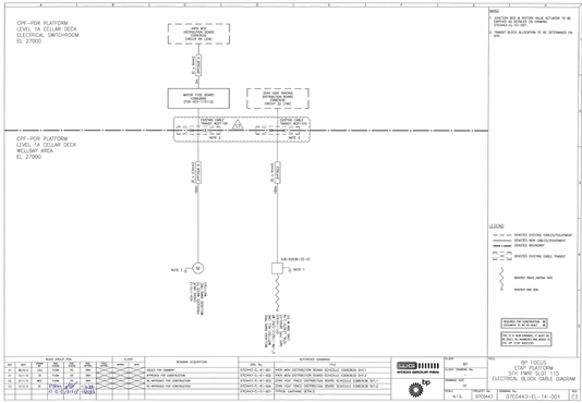
As you can see a fairly simple scope, with just trace heating and the choke Motor Operated Valve (MOV) to be tied into their respective DBs. Unfortunately when the elec techs went to tie these into the DBs, it was identified by the platform that the cabinet could not be isolated as it removed the ability to remote operate the rest of the choke valves. The following options were considered for the MOV tie in;
- Isolate the DB and have an inst tech with a radio standing next to the choke valves in order to manually operate as required. A risky option as control would be minimal and delayed. This was not considered further.
- Tie into alternative DB. Nearest DB is some distance away and it is unsure what it currently powers. More material would be required, a workpack change would be required and an investigation would be required to understand what it powers. Not considered further.
- Do nothing and wait for the next outage. This would have significant cost implications, since the rate of PWRI is limiting hydrocarbon production and is relying on the 4th and 5th in order to increase. Not considered further.
- Do nothing, but run flowlines in manual, and trim using PWRI flowlines 1,2 & 3. MLCOA.
Decision. Option 4 was chosen as the MLCOA, but requires buy in from everyone involved. It will be necessary to carry an A(Qualified) ‘punch list’ item through System Handover (SH-1), which is not really the norm and makes people twitchy, as it has been known for punch list items to be forgotten about. It also required a growth request to be submitted to get the extra work into the outage in Apr, which is already over booked.
The same issue exists with the trace heating, but an alternative DB has been identified as a temporary solution, until permanent tie in during the outage.
Instrumentation wiring modifications.
18 months ago, ABB carried out modifications for this project, specifically software upgrades and patch wiring modifications in order to get the instrumentation signals from the transmitters to the control room. Two weeks ago, we went into the cabinets to terminate the instrument wiring to find that the modifications had not been completed. See below.
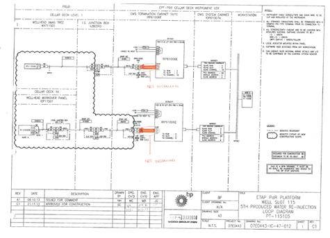
As you can imagine, there were a few phone calls and finger pointing from both sides, but essentially they hadn’t completed all what there were supposed to have done. That then turned into 2 weeks of us trying to get them to commit to dates and availability, but them not doing anything until a PO had been raised to pay them, which takes time to generate and required ABB input, which they were also dragging their heels about. Of course the discussion about why we are paying them again to do something they should have done is a different discussion. We now have someone offshore to complete the mods.
Literally as I type, I have just received an email which states that the mods required would have to be done in a shut down due to the other wiring in the cabinet. This is significant, as the chances of commissioning and putting into service the flowlines now is almost certainly impossible and will have a financial cost of c. $100k a day in deferred production.
Of course there will have to be an investigation as to why the work wasn’t carried out in the first place, I’ll let you know the outcome.
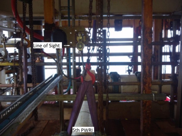
Pipe support clash with Line of Sight gas detector
A few weeks ago it was identified that there was a clash between a pipe support spring can and existing pipework which is part of the deluge system. This required a re-design of the pipe support and was moved 90mm to avoid the clash. Shortly after, it was identified that it now clashes with a LoS detector system which picks up gas leaks in the well bay, which is quite important.
It has been painful, but there is now a way forward by moving very slightly the LoS detector. This took a week to resolve and discussions with a whole host of people to get acceptance which didn’t require a separate Management of Change (MOC) procedure.
Summary
This project continues to throw up issues, which take a significant amount of time to resolve. There are of course a few questions that need to be asked;
– Why was the ABB work not completed as thought?
– Why has it only been identified now that the DB and cabinets can only be worked on during an outage
– How was a piping clash not identified in the design phase?
I will keep you posted, as the significant cost implication will cause a fair bit of noise.
