Archive
CPR Gold!!
Atkins are very good at providing fodder for Continuous Professional Development. I have a ready supply of wider industry news articles and studies to scan, over my packed lunch, which depressingly I take ‘al desko’.
This struck me as a good CPR handle, as skills shortages are surely one of the main strategic risks to the UK construction industry as it struggles to deliver the National Infrastructure Plan.
Enjoy
Legal problems…
Having left behind the big smoke in favour of a more sedate life back in Devon, I’ve joined Atkins consultancy, and am based in Exeter. Part of a global brand, the Exeter office takes the lead on local projects which offer a wide variety in scope, and has offered me to the chance to get stuck in from the off. So far, I have been involved in four main projects, each at different stages of the design process.
They are as follows:
1.Slope stability analysis on an earthfill reservoir embankment in Bruton, Somerset.
2.Production of a scoping request ahead of a planning application on Linhay Hill Quarry, extension works, Ashburton
3.Project management of a planning application for an organic foodwaste recycling plant, Avonmouth, Bristol
4.Drainage design on new school within a development scheme at Mudford, Somerset. Whilst you’re still reeling from the sheer scale and profile of these projects (Burj Khalifa 2 is next month apparently…), I will give you a snapshot of some of the planning legislation and guidance that I have become familiar with on the Avonmouth job.
Background. Wessex Water Enterprises’ business unit, GENeco, leveraged spare capacity at the Avonmouth sewage treatment works to build an organic food waste plant in 2010/11. This ‘stomach in a shed’ takes approximately 30,000 tonnes of food waste from across the wider Bristol region, and processes it into methane and digestate fertiliser. These by products are recycled in to a number of uses including fertiliser for the agricultural industry, and even to power the cities buses. Check out the link to a CBBC rundown on the plant, which is at about the correct level for my childish mind…
http://www.geneco.uk.com/Food-waste-recycling/Default.aspx
Given the success of Phase 1 of this development, GENeco wishes to submit a new planning application to deliver Phase 2 of the works. The Avonmouth development will constitute an expansion of existing works delivered in Phase 1. The proposed new development will add an additional 30,000 tonnes per year of capacity to the plant. GENeco have approached Atkins to support a planning application for an expansion of the plant.
Client Specification. Wessex Water support their own small engineering services team, and have decided to deliver some of the aspects of the planning application themselves. Whilst this has led to a slightly incoherent approach, much of the planning application from Phase 1 is likely to remain extant which should serve to de-risk this process. The scope of Atkins involvement has been reduced to the following sections of the report.
(1). Scheme Drawings
(2). Transport Statement, to include travel plan
(3). Landscape and Visual Impact Assessment
(4). Site specific flood risk assessment
(5). Odour assessment
(6). Air quality assessment
Contract. Atkins have utilised a standard form of consultancy agreement; specifically the Consultancy Services Contract. This enables the provision of consultancy services and deliverables, in which the deliverables are clearly defined. Each deliverable is priced in isolation; a clear explanation of the basis of the costings is given, including named participants and their hourly rate. Either party may request a change to the scope or execution of the services, but importantly the consultant has no obligation to perform the variation until all variations in fees and services have been agreed. In this instance, when the scope is unclear, this provides a risk share for both parties, as each development in scope can be judged on its individual merits and agreed upon in isolation. However, the key managerial issues in this example are at the local level. The scope straddles a number of functional areas within the broader Atkins organisation, and so implied in the deliverables is a project management function. However, in order to remain competitive at tender, project management fees were ‘scoped out’ and currently those costs are lost in each of the departmental fee proposals.
My role. Perhaps predictably, I have taken on the role of ‘free at point of sale’ project manager. Initially I prepared and issued Inter Unit Work Orders (a formal arrangement between departments that agrees requirement, program and costs) to each department and negotiated their program lengths and costs. This was captured in an offer letter, which was sent to the client for agreement. The tender was then awarded. I have issued a tasking order which provides an overview and initial proposal layout, with guidance on program and resourcing. I included an RFI matrix, which has enabled me to liaise with the client and key stakeholders, such as Bristol City Council, to manage the information flow between all parties. Weirdly, this has made me the toast of the town! I have also been tasked with the production of the Flood Risk Assessment, which I submitted this week aswell as Odour and Noise Assessment.
Legislation All the planning policy guidance is contained within the National Planning Policy Framework (2012). Aswell as being a ripping good yarn, it sets out all the governments planning policy in one easy to read document. This is considered a huge improvement to the system before 2012. In the context of flooding, the broad aim of the National Planning Policy Framework, March 2012, is to reduce the number of people and properties within the natural and built environment at risk of flooding. To achieve this aim, planning authorities are required to ensure that flood risk is properly assessed during the initial planning stages of any development. The responsibility for flood risk assessment lies with the developer and they must demonstrate the following:
- whether the proposed development is likely to be affected by flooding;
- whether the proposed development will increase flood risk to adjacent properties; and
- that the measures proposed to deal with any flood risk are sustainable.
Sequential Test and Vulnerability Classification. In order to establish these aims, the ‘Sequential Test’ is used to steer new development to areas at the lowest probability of flooding, with the starting point for the sequential approach being the flood zones detailed in the Technical Guidance to the National Planning Policy Framework. Development should be directed to Flood Zone 1 wherever possible, and then sequentially to Flood Zones 2 and 3, and to the areas of least flood risk within Flood Zones 2 and 3. Where there are no reasonably available sites in Flood Zone 1, local planning authorities determining planning applications for development have to take into account the flood risk vulnerability of land uses, again outlined in the Technical Guidance to the National Planning Policy Framework, Vulnerability Classification.
Risk Categorisation. Flood risk includes the statistical probability of an event occurring and the scale of the potential consequences, and the risk is estimated from historical data and expressed in terms of the expected frequency (or ‘return period’) of a flood of a given magnitude. For example the 10-year, 50-year and the 100-year floods have a 10%, 2% and 1% chance respectively of occurring in any one year, and those values are termed the Annual Exceedance Probability, AEP. However over a longer period the probability of flooding is considerably greater, hence for example, for the 100-year return period:
- There is a 1% chance of a 100-year event occurring or being exceeded in any year.
- A 26% chance of it occurring or being exceeded in a 30-year period.
- A 51% chance of it occurring or being exceeded in a 70-year period
The Technical Guidance to the National Planning Policy Framework, March 2012 defines flood zones in relation to the probability of river and sea flooding, ignoring the presence of defences, and details the appropriate land uses, Flood Risk Assessment (FRA) requirements and policy aims for each zone. The Environment Agency provides Flood Zone maps available via its website which are used as the starting point for all FRAs. From inspection of those maps, the central section of the Avonmouth site, i.e. the existing reception centre near the drainage ditch (the ‘rhine’ network) lies within the Environment Agency’s indicative flood zone 3, defined as high probability of flooding, by the Agency. The Technical Guidance to the National Planning Policy Framework, March 2012, also requires the vulnerability of the development or land use to be taken into account as the consequences of flooding may not be acceptable for particular types of development, and it defines Flood Risk Vulnerability Classification for the proposed use of development sites. With reference to that table, the proposed development land use, namely waste treatment facility, is classified as ‘less vulnerable’.
Town and Country Planning (Flooding) (England) Direction (2007) Due to some inappropriate developments being granted in flood risk areas against advice of the Environment Agency, the Secretary of State under the County Planning (General Development Procedure) Order 1995 (“the Order”) made the Town and Country Planning (Flooding) (England) Direction 2007 (the Direction) which came into force on 1st January 2007, to provide a safeguard against such cases The National Planning Policy Frameworks states the requirement for a Regional Flood Risk Appraisal to provide a broad overview of the flood risk issues across the region; in this instance the South West of England. It seeks to highlight key areas where more detailed study is required at a sub- regional level. I consulted the South West Regional Flood Risk Appraisal (RFRA), February 2007 with regard to the proposed development, and Avonmouth is considered as an area of sub regional flood risk. The area of Avonmouth, Severnside and Royal Portbury Docks are characterised by a ‘substantial coastal flood risk’, where property is at risk from tidal and fluvial flooding. Additionally, surface water drainage can be subject to ‘tidal locking’ at high tide. This risk is mitigated by tidal flood defences which are installed between Avonmouth and the Severn Beach. These offer protection up to a 1 in 100 year event. That said, the effect of climate change and the rise in sea levels is a major concern in the Avonmouth region. It is estimated that severe tidal flooding events will be six times more likely to occur by 2060 (i.e a 1 in 200 event now, will become a 1 in 33 year event).
Planning Policy Statement 25 (PPS25) Development and Flood Risk (Communities and Local Government) issues detailed guidance on the assessment and management of flood risk. Within this it directs local authorities to produce a Strategic Flood Risk Assessment for their area of administration. A Level 1 initial assessment is carried out for all the administrative area by the Local Authority to understand the flood hazard. Where this study indicates an area of flood risk, a second, and more detailed study is commissioned to collect further information of the distribution of the flood hazard. The Level 1 SFRA in this case, indicated Avonmouth as a key area requiring further detailed assessment of fluvial and tidal flood risk. The Level 2 SFRA states that the vast majority of the Avonmouth area is considered as at a high probability of flooding (Flood Zone 3a – 1% AEP river flooding or 0.5% coastal flooding). If there were no tidal defences, extensive flooding could be expected. It is also clear that the Avonmouth/Severnside area is very susceptible to tidal/surge flooding from overtopping the defences. In this instance, the sequential test demonstrates that there are no alternate reasonably available sites in areas with lower probability flooding. As stated, the development is proposed as an extension to the existing anaerobic digestion plant, and therefore needs to be located adjacent to the existing works. As the Bristol STW is located entirely in the designated flood zone 3a, there are no alternate lower probability (zones 1 and 2) which would be preferential for the proposals. The ‘Exception Test’ should therefore be applied. In this test, it can be shown that:
- The development provides wider sustainability benefits to the community that outweigh flood risk
- It is proposed on land previously developed.
- A site specific flood risk assessment will be included to demonstrate that the development will be safe, without increasing flood risk elsewhere
Next steps… My flood risk assessment demonstrated a medium to high risk from a tidal event, which is increasing with climate change. Fluvial flood risk is medium. The Avonmouth flood defences in the immediate area mitigate this risk somewhat, but The Environment Agency don’t own the full length, and therefore the maintenance scheme is hit and miss at best. I therefore recommended that the residual risk remains at medium to high. I approached the client informally ahead of the publication of the risk assessment to recommend further consideration to mitigation measures. I was told in no uncertain terms that there was no aspiration for this, and certainly no budget at this stage, and given the ‘less vulnerable’ status of the industrial unit didn’t justify further expenditure. Ill still be taking my wellies on my site visit on Wednesday….
Progress or Quality?
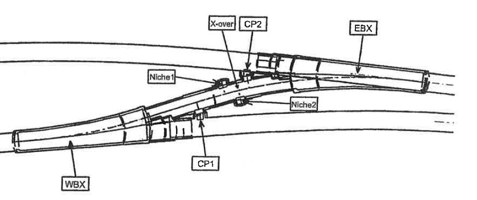
Having treated my self to a weeks ‘summer’ leave last week, I returned to what can only be described as widespread mayhem on the secodnary lining team. Three members of the team had left, including my line manager. Rats and sinking ships. I am still employed as a section engineer on the ‘binocular section’ of the crossover between the two running tunnels. The tunnel design and construction varies over its length dependent on function. For example, the running tunnels which maintain a uniform shape over a long distance, are driven by tunnel boring machine and lined with pre cast concrete panels for speed of drive. Enlargement works foR platform tunnels and concourses, including irregular shapes are ordinarily excavated and lined with steel fibre reinforced sprayed concrete. Uniquely, the binocular section uses a sprayed concrete primary lining, in composite with a cast in situ bar reinforced secondary lining. I will focus on this here. Binocular Section Function. In operation, the running tunnel will divide into two; the left hand side will form a crossover to the opposing running tunnel. The binocular sections are located in the areas noted EBX and WBX, at the point where the tunnel divides in two.The design is also shown in section, and is mirrored westbound and eastbound. 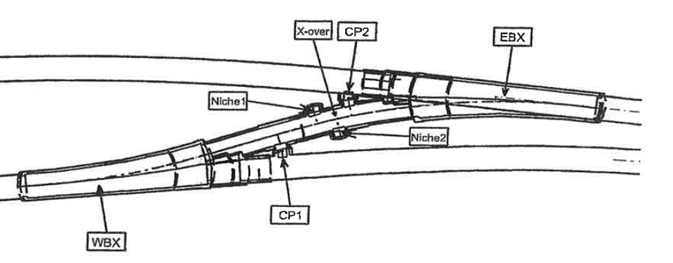
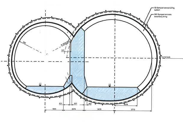 The internal profile, defined here by the bold line, designates the secondary lining, which is all cast in situ. Design. The front face of this section details a relatively large span at approximately 12.6m. This would be considered challenging to complete entirely in sprayed concrete. But the ‘figure of 8’ design creates high stress zones at the confluence of the two tunnels. This requires support which is designed in the form of the ‘binocular wall’ shown as the upright in blue. You will note that in comparision to the remainder of the secondary lining, the wall itself has large proportions. This design copes with the temporary state during the excavation of the second tunnel and prior to ring closure. Sidewall Issues. Aside from the day to day frictions that I will not cover here the casting of the invert, headwall and binocular wall sections passed largely without incident. However, the right hand sidewall was poured in my absence, with some issues. The profile of the sidewall is formed by the use of bespoke poystyrene void formers, which are designed and laser cut by a specialist contractor. They are supported by RMD Kwikiform temporary works, again designed by sub contractor. Despite being contracted out, temporary works repsonsibility falls to us, so I got involved here to check design calcs, and made some adjustments for buildability purposes. Designs are shown below
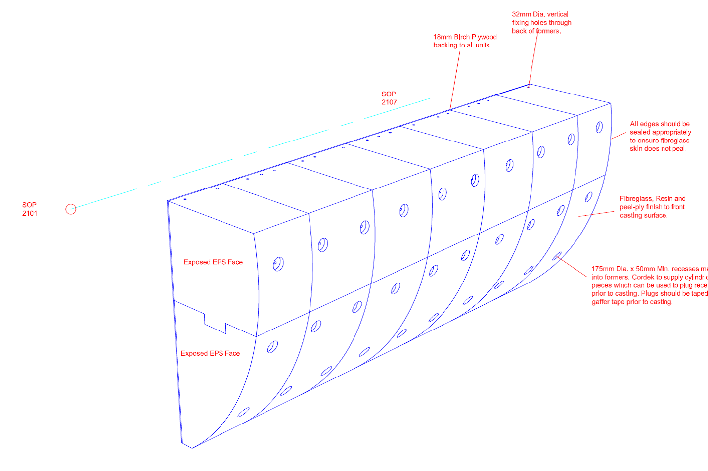
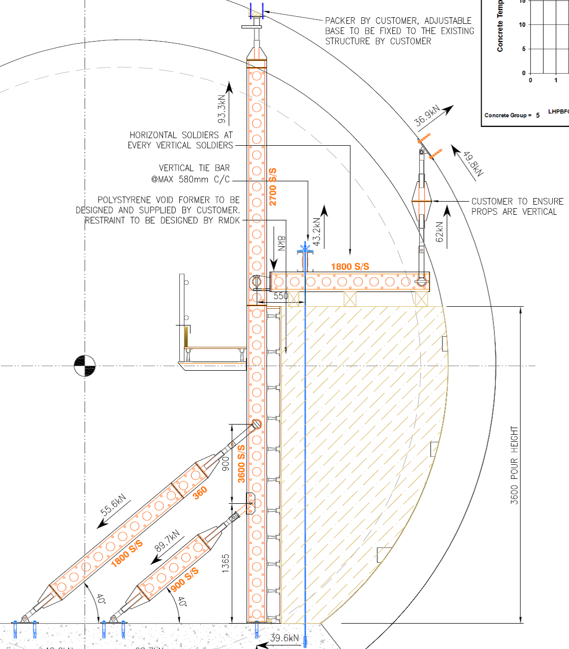 You will note that the profile presents a tricky detail for the pouring and vibration of concrete at the lowest point, particularly given the congested steeelwork incorporated here. Way ahead of this pour, I sought to preempt this issue by designing, in conjunction with the supplier, a self compacting mix, which I trialled and had approved. This was supposed to replace the existing mix, which was also susceptible to entrapping air due to the type of polyfibre it contained. (See previous blog about mix designing – a delight). Thus I went on holiday happy that I had forecast a design risk, conducted some analysis, came up with a solution and communicated it effectively. (See John, I was listening…) I returned to this….
  The poor resolution on this phot doesnt give you the full joy of this. You may note pock marking across the bottom 2/3 of the wall. This is caused by a proliferation of air bubbles trapped in the lower section, exacerbated by poor vibrations. As it turns out, the old mix was used despite my amended activity plan explicitly stating the new mix to be used. The entrapping of air is quite obvious here. I suspect, if the wall was cored, that the mix would have a relatively low density, and may fail on compressive strength as a consequence. You will also note the cold joint which runs the length of the wall. Apparently, pre planned road closures causing traffic in London, delayed the follow on wagons by approximately 4 hours between pours. With no engineer on site when it finally arrived, the site foreman continued the pour based on ‘whether we can still get a poker in the mix’. Conclusions The loading path in this section of wall puts the wall predominantly in compression. That said, there are performance requirements pertaining to flexural strength. Assuming there are no major voids at the cold joint, this should not present an immediate structural problem. My concern is the threat of water intrusion and consequent acid attack in the high sulphate environment of our local ground, over a 120year design life. However, it is likely that these concerns remain on the aesthetic rather than the structural in this instance. The air entrainment is a bigger concern. Although the contractor kindly offered to patch repair the surface to bring it in line with the clients specified surface finishes, I feel like they are missing the engineering risk. I demonstrated the effect on compressive strength that a lover volume can have in my failed mix design trials, and I suspect in we were to core this, we may find voids and poor encapsulation of the rebar, along with a low compressive strength. The client has yet to request this but Im certain it will. I find it hard not to be deeply frustrated and cynical about all this. All of these issues were foreseen and planned for, but coherent planning of a task from start to finish is simply not in the culture here. A single responsible person for these task s is not easily identifiable and noone is held to account. A common theme throughout my attachment here is that progress always trumps quality, and even cost. These problems were caused by not following the instructions, and a lack of engineering oversight, combined with a rigid application of quality, through the inspection and test plan that I wrote to govern this. The rush to complete, and consequent mistakes made have achieved a delayed program, and extensive rework. We are under an NEC (C) Target Cost contract, so as long as we raise this issue through a Non Compliance Report, the ‘pain’ is shared with the client. So incompetance on our behalf of the contractor has led directly to waste of public money…not only frustrating, but actually quite immoral. In other news, I’ve found something as uncomfortable, as a John Moran Q&A. Tough Mudders Electric Shock therapy
Full of hot air….
No doubt you have all had trouble sleeping recently. Understandable…waiting in trepidation for the outcome of ‘McGuirk’s Magical Mix’ trial for the cast in situ secondary lining! In the seminal works, ‘Red Card Moments – Parts 1 and 2’, I detailed the genesis of this mix, following the realisation that there was a national shortage of Pulverised Fuel Ash (PFA). So like a slightly confused contestant on Great British Bake off, I was set the challenge of developing a new recipe for self compacting mix by the site sub agent (who is no Mary Berry!). This mix was to include Ground Granulated Blast Furnace Slag (GGBS) as a cementious filler, in place of PFA. The mix design is as follows:
kg/cubic metre
Ordinary Portland Cement – 270
GGBS – 180
Agg (Limestone, 20mm, 10mm, 4mm) – 1300
Marine Sand – 325
Filler – 100
Admixtures including superplaticiser (water reduction for the low water/cement ratio), stabiliser (modifies viscosity, and eliminates segregation) and retarder(controls the rate of cement hydration). An importanly, 2kg of polypropylene fibres for passive fire protection.
Results
This table shows the performance requirements specified by the client…and how my mix got on!
| Performance Requirement: | KF10 rev 10.0: | BFK024A SCC |
| Cementitious Content | > 320 kg/m3 & < 450 kg/m3 | 450 kg/m3 |
| Water / Cement Ratio BS EN 206-1: 2000 | < 0.50 | 0.50 |
| Density | >2300kg/m3 | 2207kg/m3 average @ 28days |
| Target Flow BS EN 12350-5: 2009 | To be determined during site trials | 500 mm |
| Concrete Temperature | 15°C – 35°C | 26°C |
| Early Age Strength Development | C8/10 @12hours or | 6MPa (achieves 9.2MPa at 24hrs)(please see general comments) |
| Long Term Compressive Strength BS EN 12504-1: 2009 | 28 days > C32/40 | 43.8 MPa(Must exceed specification by current margin, 7.5MPa minus 3.5) |
| 90 days > C32/40 | ||
| Concrete Shrinkage ASTM C341/C341M-06 | <0.03% | 0.003% |
| Exposure class | XC3 | DS2 |
Many of you will not be surprised to hear that despite a valiant effort…it failed. Two criteria. Density and compressive strength.
Analysis
The strength of the concrete is influenced by the water/cement ratio and the relative volume of air in the mix. All Crossrail mixes that I have encountered so far have a specified w/c ratio of <0.5 and in the main, have easily achieved the required density. This mix achieves a figure of 0.5. Whilst I would have preferred a slightly lower figure to achieve a greater strength, this is still within specification, and therefore is not affecting the density in this instance.
The cementitious content adheres to the specification of no more than 450kg/m3, and so cannot be increased. Further, at no point can the mix achieve a temperature of 70degrees C during curing. Using thermocouple data loggers I recorded a peak temperature at the core of 66degrees, so I dont feel I can increase the proportion of cement for fear of too much heat gain.
Therefore, I am focussing my efforts on the volume of air in the mix. The low density may indicate a higher than normal volume of air in the mix. Crossrail have an air entrained mix which is used as a sacrificial medium for the Tunnel Boring Machines to ‘pull’ their way through the station boxes on their drives. The air entrainment has left them with a similiar density to my mix at around 2100kg/m3. This mix is designed to have a relatively low compressive strengh to allow the TBM to easily plough through it. I therefore suspect something in the mix causing it to retain air voids which reduces the density, and further the compressive strength.
Polyfibres
By comparison to other mixes in the project, the only real variable in this mix, is the addtion on polyurethane fibres. Following a series of high profile tunnel fires and the increased threat of terrorism, the safety of underground structures have gained public atention. Polypropylene fibres have been developed as a means of passive fire protection to prevent explosive spalling, and maintain the structural integrity of the concrete.
How do they work?
This is quite interesting…so much so that I found myself spinning the dit to my girlfriend at the weekend…before I had a moment of clarity, whereupon I fell silent for fear of getting chucked!
Imagine the concrete is exposed to high temperatures, such as those in a tunnel fire, or indeed my fire trials (Refer to the tour de force that is “I am the god of hell fire!! (testing) for more details). In high quality concrete,t he density prevents the moisture contained within the concrete lining escaping quickly enough. Any voids that are present will become saturated. The heat will gradually increase and overtake the moisture front, whereupon the moisture will vapourise and increase the pressure in the body of the concrete. This increased pressure can ultimately lead to explosive spalling.
Polyfibres are introduced to increased permeability during heating and ultimatley reducing pore pressure. At approx 160degrees they will begin to melt, before disintegating at about 360degrees. This has the effect of providing millions of capilliaries in the concrete which allow moisture to escape. Brilliant…
However….
Having been tipped off by a guarded response by the manufacturer, it seems the particular brand of fibres…IGNIS…have a tendency to trap air in the mix during curing. As a fag packet calculation, a percentage air change of 1% in your mix can affect the compressive strength by as much as 5%. As the mix had cured there wa no means of conducting an air entrainment test on it, but this confirmed in my mind that this was a prime suspect.
Next Steps.
The pressure is definitely on. We are programmed to pour this mix in the permanent works in 5 weeks time. 28day results, plus a 2 week contracted response time from the client for material approvals, puts us behind by a week.
I have initiated two trials, whih were poured this morning. The same mixes, but with two alternate fibres: one from the same manufacturer, one from a competitor. Initial results as follows:
Fibremesh 150.
Slump/Flow. – 660mm
Ambient temperature. – 15.7°C
Concrete temperature. – 17.6°C
Fresh Density. – 2275
Air Content. – 2.1%
M320P 32F.
Slump/Flow. – 640mm
Ambient temperature. – 14.5°C
Concrete Temperature – 19.7°
Fresh Density – 2270
Air Content – 3.7%
NB. The air entrainment test is not a requirement byt specification, but I requested it given my theory that air content is at the heart of this. Using previous mix performances, and the fag packet from above, I reckon the percentage of air content in the first, failed mix could have been upto 10%. The result above are a good start
Testing
I have taken a total of 30 cubes over the two tests, which will allow the following (increased) testing regime. Those required by the spec are highlighed. In addtion, cores will be taken at 28days the test dry shrinkage.
12hrs – 3 Cubes – Crushed at 27 Aug 14, 1930
24hrs – 3 Cubes – 28 Aug 14, 0730
7 Days – 3 Cubes – 03 Sep 14
14 Days – 3 Cubes – 10 Sep 14
28 Days – 3 Cubes – 24 Sep 14
56 Days – 2 Cubes – 22 Oct 14
(2 spare)
In order to expedite this, I have gained provisional agreement from the client to submit a Materials Compliance Report at 14 days in the hope that I can show a marked improvement in material strength against the first mix. If Im really lucky it may have gained its 28day strength by then, in which case they will approve subject to dry shrinkage results at 28days, meaning McGuirks Magic Mix will be holding up the ‘cross’ in Crossrail!
Red Card Moments – Part 2
Following the PFA ambush of last week, BFK have found themselves backpedalling to find a solution. A contract wide issue that is still being discussed by senior management up in the ‘Deathstar’; however, down at Fisher St, we critically need a self compacting mix trialled and approved before the middle of next month, should the PFA risk manifest itself. So with an empty chair where the materials manager used to sit, and our Materials Tech jumping ship, we were down to a cast of one….
Requirements
The client’s materials and workmanship specification for cast in situ dictates mix design and trial requirements as follows:
Temperature: 2 key points:
- At the time of deposition of the concrete, shall be in the range 5 degrees and 30 degrees. (A planning figure for expected heat gain is approx 10 degrees per 100kg of cement per m^3. Our mix contains 270kg per m^3, and therefore a 27degree heat gain on a 30 degree ambient temp would remain in spec because….
- The upper temperature limit of the placed concrete should not exceed 60 degrees C. Designed to minimise the risk of thermal cracking.
Testing. During trial mixtures need to demostrate results for:
- Compressive Strength
- Consistence
- OvenDry density
- Fresh Density
- Bleed
- Segregation
Testing is conducted on at least three specimens from at least three batches, andis in accordance with Annex A of BS EN 206-1:2000 and is a thrilling good read!
Temperature Testing
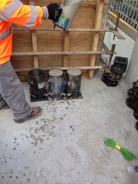
In order to demostrate the temperature gain and the max temp value, a 1m^3 sample is poured into a ‘coffin’. This coffin is installed with thermocouples which will measure the core temp, surface temp and the ambient temp during curing. This setup is shown below.

1m^3 of self compacting mix. Note green thermocouple wiring
Temperatures will be recorded by the data logger at a rate of every 30mins for two weeks.

Ruggedised data logger will record data over a two week period
Concrete Strength
Requirement:
In Situ Concrete strength requirements, C8/10(12hrs), C32/40(28 days)
Test cubes will be crushed at the following frequency, in accordance with the specification. 1 x 12hr, 1 x 24 hr, 3 x 7 day, 3 x 28 day, 3 x 56 day. This frequency will give indicative early age strength gain for reassurance, followed by the criteria test at 28days. This allows concurrent activity…I have written the Materials Compliance report for approval by the client on the basis of the early age stregth gain;it has been approved, on the caveat that it does gain the 28day strength. If this criteria is not met at 28days, the 56 day cubes will be crushed, and the results will be demostrated to the client for approval.
Consistence
A slump/flow test is conducted in accordance with BS EN 12350-2. A critical feature of the self compacting mix in this instance is the workability. The location in the works dictates that the concrete pour would be difficult/unsafe to effectively vibrate into position, and thus a flow to allow movement into these areas is an imperative.
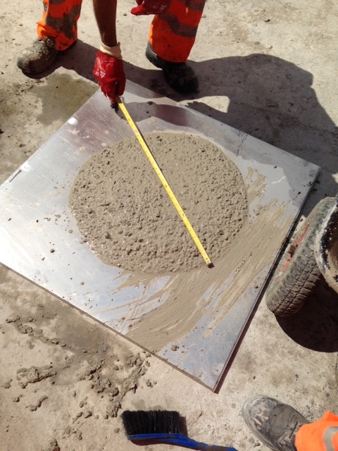
Note sample has been allowed to reach its full diameter at measurement.
The specification requires samples to acheive a flow result of 490mm – 650mm. This sample achieve and average measurement of 550mm. Additonally, bleed was visually inspected on this sample and considered to be the within limits
Segregation
Three cylinders of 150mm diameter and 300mm height were cast for the batch. The cylinders are then sliced into 6 sections of equal thickness. The mass of each slice is then measured and the density calculated to determine density variation throughout top to bottom of the sample. The average variation from the top to bottom of the cylinder shall not be greater than 10% of the mean density of the concrete

Segregation in the sample will be demostrated by aggregate gradually moving to the bottom of the cylinder, thus increasing the average density to the bottom.
So with help from the concrete supplier, we’ve designed and tested a self compacting concrete mix, that thus far is performing as required by the specification. If it continues this way, my mix design may well be used throughout cast secondary lining throughout the western tunnels. Terrifying….
BUT…before there is a mass protest/retirement at PEW!
Just as I was about to publish this, I’ve just received a slightly panicked email. Due to concrete suppliers switching to GGBS after the PFA shortage, and a problem with the discharging of ships at the Port of Entry at Tilbury, UK GGBS stocks are currently at 30%! Brilliant…
Red card moments!!
One of the constituent parts of the plethora of concrete mixes used on the Crossrail project, is Pulverised Fuel Ash, or PFA. A waste product from coal fired power stations, the material is ground down to a fine powder, mixed with heated air and burned. This forms a proportion of the material (about 20%) into fine glass particles which are separated from the remaining material.
This material has a number of uses in the construction industry;predominantly as a construction fill; as a raw material in cement manufacture, and most pertinent to me as a partial replacement to cement in concrete. This has a number of benefits:
Economic -reduction in the overall quanitity of cement purchased, and consequently a reduction in cost by using a waste product (relatively very cheap to transport from the power stations)
Environmental – green credentials in recycling waste product without the need to dispose of the stuff.
Technical. A number of technical benefits occur from the use of PFA as a constituent of the concrete mix, including:
– improved long term strength performance
– improved durability through reduction in mixing water
- – improved cohesion and workability for a given water content
– improved surface finish
– improved resistance to sulphate attack(ground water levels are on the rise in London, and in my little corner of the Lambeth Beds, there is an increased risk of oxidised pyrite leading to corrosive acidic groundwater)
– reduced heat of hydration (important in our specification as the concrete musnt remain below 60degrees during curing…difficult in summer…our tunnel reached 42degrees yesterday!)
– reduced shrinkage and cracking (see above!)
– reduced bleeding
– resistance to alkali-silica reaction
All in all, its good stuff to have on board…
So why do I tell you this? Keen to hear from all you concreters out there about reduced stocks of PFA in the UK. Our supplier CEMEX has withdrawn all supplies without notice. Without all the facts, it seems that it is a direct result of many of the coal fired power stations switching to gas. Hansons, the concrete supplier, run out of PFA as at today, and having explored all other options with no joy, have advised that we revise our mix designs sharpish! This affects all their customers, not just Crossrail, and I would imagine other suppliers are feeling the pinch too. Anyone else had this buzz? (When I asked Steve whether he’d had the email about the PFA, he point blank refused to return to Chatham to run a mile and a half! Thats not what I mean….)
So what?
Hansons are contracted to supply us with concrete to specification. They ultimatley are not achieving that, so contractually it seems very simple. However, the pressure of the program mean that the blame game is slightly moot. This apportionment will no doubt will be thrashed out later, but right now it’s in our interests to review these mixes and return to production
In terms of where the blame does sit and who ultimately wil pay for this…does this count as a ‘force majeure’, being as it was, unforeseen?
Come back Mike Burton…all is forgiven!
I am very proud to say that I am following in the footsteps of Mike Burton. I don’t mean drinking too many ‘Quad Vods’ at Jester’s nightclub, telling war stories to impressionable students…I mean in making my mark CrossRail’s Fisher St shaft. Good to finally be on site full time…
Overview
The Fisher St project consists of two distinct sections of works;
Phase 1 was the excavation of a large access and maintenance shaft, 25m in depth running from ground level to running tunnel. Adits on the northern and southern sections of the shaft adjoin the east bound and west bound running tunnels. Mike saw this section of works completed throughout his time here. Its function during concstruction is to act as access and egress for equipment (including the removal of 2x1000tonnes tunnel boring machines), material, spoil and personnel aswell as a mean of escape. In operation it will act as a maintenance shaft and proivide ventilation to the running tunnels
Phase 2 is the construction of the cross over section. The only point throughout the 42km of line that the two tunnels interact, the section will be used for train maintenance, in the event of a breakdown, in order to clear the line. Work is underway to excavate the ‘binocular sections’…essentially the section on each running tunnel where the tunnel divides in two to form the crossover section. My part of ship from here on in…see the overarching plan for the picture to paint my 1000 words.
Ground
I remember the Great Orator mentioning that the ground is actually quite fundamental….he mentioned it once or twice. The nature and engineering behaviour of the ground in tunneling is obviously critical to the design considerations of the underground structures. Crossrail tunnels have been bored at an average depth of 25m along their length, with the odd fluctuation to avoid existing underground structures. The tunnel boring machines and station tunnels and caverns have been bored/dug with relative ease due to the excavations being conducted largely in the London Clay Group. Having looked at some of the ground investigation data, it seems that this consists of stiff or silty clay ranging right through to mudstone. These Palaeogene marine deposits, I’ve been assured, make for an excellent tunnelling medium, due to their relative homogeneity offering some predictability, and their short term stiffness, which allows brief unloading without collapse, ahead of stabilisation with SCL.
However, in the Fisher St/Farringdon area, the base of the London Clay sits at approximately 30m below Ordanance Datum. This area coincides with a ‘busy’ underground infrastructure network (proximity of Central and Piccadilly Lines, aswell as numerous underground services) which constrains the allignment depth. You will see from the Geological section above that just at the point of constructing arguably the most complex section of works in the allignment, we pitch head first in to the Lambeth Group.
At this stage, its probably worth thinking back to the days of the McGuirk Bluffing Face…a slight nod of recognition toward said lecturer as if I was following, when internally I was in a flat spin. Well, the same thing happened when I was told this; as if I understood immediately the implications of it…I didn’t. So I did some reading!! Yea alright, stop laughing….
This is what I learnt….we’re predominantly in the red/brown or green/grey ‘Upper Mottled Beds’, but there is quite a bit of other stuff (technical term); from fine silty sands, shell beds and sandy flint. Bottom line, its a bit of a mess; in contrast to the relative homogeneity of the London Clay belt, this material is vertically and horizontally inconsistent. For tunneling, this presents risks; potentially water bearing, the excavations could cause a flow of material along failure planes as they are uncovered, major face instability prior to concrete spraying, and greater than expected surface settlement with associated damage to surface structures in prime central London real estate.
The Tunnel Boring Machines have passed through the allignment, without reported incident, and as such I have had a few raised eyebrows for asking what the perceived risks are in relation to our excavation. This would be ok…but I since discovered that the TBM has no means of recording the nature of the ground that it passes through, for its properties, contamination or indeed the ground water regime. So essentially, we’re operating solely on a triangulation of two boreholes located 30m and 20m distant from our crossover section, and a baseline statement in the Geotechnical Baseline Report that the lower aquifer on our location is approximately 30m below the excavtion and is therefore of no significance.
Groundwater
I think that the proximity of the borehole data gives us a fair idea of thewhat the enlargement excavation will uncover, so the primary risk will be in the groundwater regime. We are aware that the Lambeth Group is likely to bear isolated pockets of water; so the water is anticipated but the quantity is unknown. So this leads to a number of risks, (based entirely on ripping off Johns notes…)
- Potential for inundation into the tunnel as a pocket of water is uncovered.
- The Lambeth Group is non-cohesive, so this may lead to an increased risk of heave in the tunnel invert if the resistance to this uplift is less than the head created by this water
- Instability in the face due to ground movements caused by pore water pressure.
I must admit, I’m not yet sure what we’re doing about this, if anything, and so I will revisit in future blogs….
What next?
A part of the Phase 2 works, the binocular section on the westbound tunnel (WBX) has been excavated and the primary lining sprayed.
The construction of the cast in situ secondary lining works will now go ahead, with me firmly installed as the section engineer! Blog to follow….
I am the god of hell fire (testing)!!!
In my final action as a Materials Team geek, beofre moving down to site, I found myself responsible for demostrating the competancy of the fire protection in the tunnel lining. This has become a bit of a poisoned chalice, as the testing the first time around was so badly managed and delivered that it was deemed uncompliant by Crossrail Ltd, at a cost to the contractor of £48000. In the context of this contract, pocket change, but in terms of reputational impact, quite costly. As chalices go, poisoned ones are my least favourite…so feeling a little bit like the fall guy, I got stuck in…
Regulating Layer Function
As discussed in previous blogs, the tunnel lining comprises a series of layers which fulfil a specific and discrete function; structural or serviceability related. The two regulating layers are designed to smooth the substrate, which in this case will be the primary and secondary layers consisting of a Steel Fibre Reinforced Concrete mix. The smoothing function covering rogue steel fibres is pertinent in the case of primary lining regulating layer, as the polyurethane waterproof membrane will be applied over it, running a risk of the steel fibres protruding through it, and casuing discontinuity. A secondary consideration is to prepare the surface for efficient waterproof application. Cratering, or large undulations in the profile of the primary lining will lead to an excessive use of spray waterproofing, which is an expensive construction material. (£20 per kilo)
Typical Lining and Thicknesses
The secondary regulating layer will form the innermost sprayed layer of tunnel lining. In addition to providing a fibrefree surface as above; it will also provide the critical function of passive fire protection to the tunnel structure.
Specification
The secondary regulating concrete mix is a relatively simple design specified to achieve C28/34 at 28 days, with a 600mm flow measurement on arrival at site. This mix has an increased retarder (1%HCA from 0.5%) from the original design after issues with the concrete life in the early stages of the trials.
In the context of the fire protection, the mix contains polypropylene fibres, or polyfibres. Following the first fire in the Channel Tunnel , in 1996, a major test program was undertaken by the Rail Link Engineering Design Group on behalf of the Channel Tunnel Rail Link. It demonstrated that the use of polyfibres in concrete significantly reduced the phenomenon of explosive spalling, and thus maintain the integrity of the protection of the structural lining. Polypropylene fibres are now specified in most public use tunnels and underground spaces.
Testing
1. Sampling. The specification dictates that the samples should replicate the tunnel lining as closely as possible. To that end, moulds were constructed from low absorbing plywood to the dimensions dictated: 1700x800x500mm. The panels would then be constructed using a 450mm thickness of secondary lining mix, followed by a 50mm layer of sprayed regulating mix. Two panels were fitted with conventional reinforcing bar, to replicate areas of cast in-situ secondary lining, whilst two were constructed with steel fibre reinforced spray secondary concrete. Thermocouples were installed to measure temperature at the location on the rebar, and at the interface between secondary and regulating layers. The phot below shows rebar supports which hold the thermocouples in place as dictated by the specification
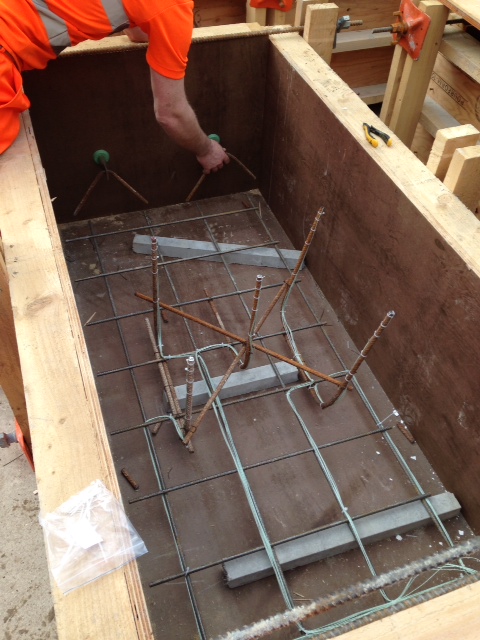
Fig 1. Low absorbing ply moulds, with thermocouple placement and lifting eye detail
2. Storage. The secondary layers were poured whilst the moulds were flat. Once cured, they were lifted to near vertical and sprayed with the regulating layer, at pit bottom in order to replicate closely the conditions in the tunnel. The moulds were struck witin 24hrs of the construction and the panels were then shrink wrapped for protection and to restrict the evaporation of any moisture from the back and sides of the panel. The panels were then lifted and transported to the BRE facility in Watford (a journey of approximately 22 miles) after 1 week. The samples were unwrapped and moved to a storage area. The temperature and humidity were controlled for the remainder of the 28 day period at 40°C and 60% humidity.
3. Test Description. Test samples are each exposed to the same temperture/time exposure, as per the EUREKA fire curve dictated by the specification. The test rig is shown in Fig 2, below and the specified target temperatures and allowable deviations shown on the curve, here EUREKA TempTime Curve
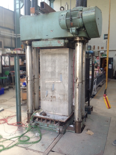
Fig 2. Test rig. Rear of the sample in view
Test Procedure
- Sample transported from controlled storage and weighed prior to test
- Specimen is placed in test rig (500 tonne compression machine) and loaded to an applied axial stress of 5MPa, in order to replicate the hoop stress seen in the tunnel lining.
- The furnace was brought against the face of the specimen and edges are sealed to prevent heat loss.
- Specimen is then heated in accordance with the EUREKA curve using a gas fired furnace. Controlled cooling will take place as part of the curve.
- Following the test, the nature and extent of spalling would be recorded
- Cores to be taken and crushed to test the residual stregth
Acceptance Criteria
The regulating layer would be deemed compliant if it adheres to the following criteria:
(1) The surface regulating layer is to be considered as sacrificial. The depth of spalling of the surface of the main secondary lining shall not exceed 25mm.
(2) The temperature recorded at the level at which the waterproofing layer will be installed should not exceed the temperature at which it may degrade, as advised by the manufacturer of the materials.
(3) Concrete cores- compressive strength of the concrete samples should not be less than 70% of the original design compressive strength at 28 days
(4) The temperature recorded by thermocouples attached to the reinforcement should not exceed 450 °C.
Discussion
In the event no spalling was witness during the test, with the exception of the 3rd test. Here, the spalling was restricted to a localised area towards the bottom half of the test panel. This occured relatively early in the test (18mins). This caused some consternation, but on inspection the spalled area was less than 25mm thick, so in fact the regulating layer had performed its function: as a sacrificial layer. No damage was recorded to the secondary lining.
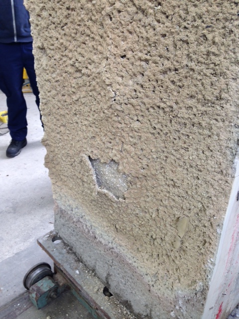
Fig3. Minor spalling in regulating layer only
BASF specification for MasterSeal 345 (waterproof membrane) advises that the product begins to degrade at approx 250degrees C. The highest recorded temperature at the interface between secondary lining and reg layer was 50 degrees and therefore well witin the safe envelope to avoid degradation of the waterproof layer
Cores taken subsequently was mandated to demostrate at least 70% of the 28 days strength of 28 N/mm^2. In fact the lowest recorded stregth was 65 N/mm^2, easily fulfilling the residual strength requirements.
Finally, thermocouples at the extreme end of the rebar, closest to the heat source recorded temperatures not exceeding 120degrees…well within the 450degress advised by the manufacturer.
The test result was a success, and following submission of the Materials Compliance Report, was accepted by Crossrail. In fact, what this demonstrates for me is that in the event of a fire in the tunnel, the structural integrity of the lining will remain intact, thus allowing escape and avoiding catastrophic collapse. However, and perhaps significantly, the test suggests that the cost of remedial action to bring the tunnel back into action would be minimal by comparison. Without degradation to the secondary lining and waterproof membrane, the cost would be in the re-application of the relatively cheap regulating layer, at a thickness of 50mm.
Strong as a Kit Kat – Part 2
The last blog saw me trying to understand the issues surrounding the high failure rate in the concrete in the primary lining, with respect to flexural strength. In a pincer movement reminiscent of the Zulus at Rorke’s Drift, Richard and John exposed my mild bluffing surrounding the testing procedure….
So here is me attempting to be John Chard…
Why test for flexural strength?
Concrete is a brittle material with a low tensile strength. Adding steel fibres to the mix will enhance toughness and ductility defined by the BS as follows:
Toughness – the ability of fibre reinforced concrete to sustain loads after cracking of the concrete ie its energy absorption capacity
Ductility – general ability of the material to sustain load beyond a yield point that defines the limit of elastic behaviour (onset of cracking). (Concrete without reinforcement would be brittle and demonstrate an abrupt loss of strength beyond elastic range.
The sprayed concrete that delivers the structural propeties of the tunnels is steel fibre reinforced (SFR).This ensures that the structure is able to sustain significant ground movements without sudden brittle failure. Therefore the trials procedures will seek to test the ‘Residual Flexural Strength’ ie the flexural tensile strength retained after cracking.
Testing
The CrossRail specification for Sprayed Concrete Linings specifies BS EN 14651 as the test method for approving:
1. Flexural Strength
2. Residual Flexural Strength
The test beams are centrally loaded as shown below, by the 3 point method. The specimens are notched at mid span to induce a crack via stress raising
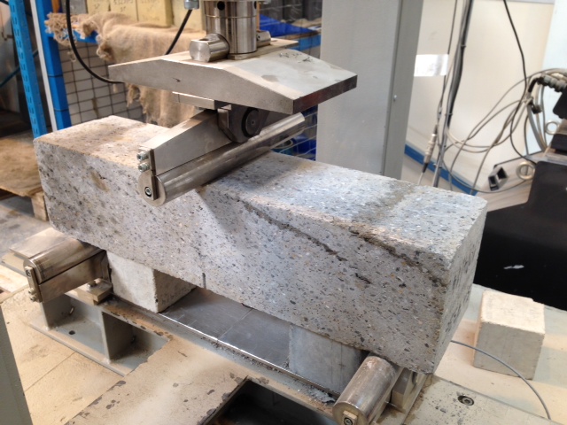
Performance of the test sample is specified by the relationship between the applied load and the Crack Mouth Opening Displacement (CMOD). This measurement can either be measured directly, or calculated in terms of central deflection
Measurements are taken as follows:
F(L) is the load corresponding to the limit of proportionality (LOP)
F1 @ CMOD1 = 0.5mm
F2 @ CMOD2 = 1.5mm
F3 @ CMOD3 = 2.5mm
F4 @ CMOD4 = 3.5mm
The slide shows a typical graph of load, F, against CMOD (BSEN 14651:2005)
Flexural Beam Test Correlation
Flexural Strength
f(L) is calculated in terms of the centre span load, F(L) as follows:
f(L) = 3FL/2bh
h = depth of beam above the notch
b = section width
L = span
Residual Flexural Strength
Crossrails specification tests values of residual flexural strength @ deflections of 1mm and 4mm respectively. However, this is not measured directly, and is measured as a CMOD, which adds an approximation to the calculation (I’ve asked the test centre why they do this…awaiting response). At these values, the beam must retain values of 1.8 and 1.4 respectively.
REFLECTIONS
1. CMOD v Deflection. Other than reliability of measurement, I dont know why CMOD would be used over direct deflection measurement (yet). Whatever the reason, the approximation adds a level of uncertainty that we can ill afford. The example test result above shows a beam which has failed, by a tiny amount, and which is typical of many of the beam failures. Perhaps a wider understanding of this testing method may mean that a tolerance is imposed such that this group of slim failures may edge over the line and achieve a pass?
2. Testing Method. Prompted by the Great Orator, I considered the 3 point testing method as discussed above. This method implies a failure method of coexistent shear and bending. 4 point testing methods for pure bending are specified in the EFNARC beam test (European Federation of Producers and Applicators of Specialist Products for Structures). The BS EN 14488 beam test largely adopts this method, and is mentioned in the CrossRail spec under structural requirements. I’m wondering whether the performance requirements were designed to one test procedure (4 point), and the 3 point test, and its differing pass criteria, were defined for use?
Am I John Chard yet????????
Strength of a kit kat!
Throughout my time here on the materials trials team, a constant headache has been the high failure rate of the flexural strength beam tests. The flexural beam tests for fibre reinforced concrete in the primary lining have been failing at a rate of ~40% at 28 and 90 days. For comparison, BFK understand that across all other Crossrail SCL works the rate is down at 5%. It turns out this issue has been going on for months prior to my arrival. The issue has become toxic, with a number of different and conflicting opinions. Unhelpfully, the issue has now become so prevelent that it is being formally discussed and debated in too many forums. Finally, CrossRail have issued an ultimatum…BFK are to provide a robust explanation as to the cause/causes of the high failure rate including action plan by the end of the month, or all SCL work stops.
So here’s what Ive learnt….
Testing.
BS EN 1465 dictates the test critieria. In outline, a set test panels of concrete are sprayed at the face of the advance, at a rate of 1 set/month. Each panel is cut into 3 beams, which are wrapped and sent to TestConsult…our subcontracted test laboratory. The beams are notched at mid section to induce a crack in the centre of the beam. The beam is then tested to failure using the 3 point testing procedure on a Universal Testing Machine….note the band layers in the top right of the beam
As the beam fails, note the faint band layer below which crosses it from approximately 10 – 4 on the clock face. The crack appears to follow the band layer as a failure plane up and to the left. The beam is now loaded off centre, perhaps contributing to a more rapid failure.

The test is dictated by the CMOD or Crack Mouth Opening Dimension. Measured in mm by electrical contacts, an average test result looks like this.FAR 0053-10.Beam & Cores. Note here the Residual Flexural Tensile Strength section…two snapshots are taken…at a deflection up to 1mm, the specification dictates the CMOD must be above 1.8, whilst up to 4mm the CMOD must maintain above 1.4. CMOD is a function of width of crack to length of crack
Action Plan
BFK are beginning to pull together an action plan to resolve this issue. Due to the complexity of the potential contributory factors, they have cast their net widely. Pulling in advice from their parent companies BAM Nuttall and Wayss & Freitag, aswell as specialist suppliers Normet/Tam alongside our own design team. The collective thoughts have distilled down to 6 areas of consideration:
1. Materials/Mix Design.
- A ‘sandy’ texture has been observed on the sprayed material when cured, which may contribute to the laminations. It is possible that this is due to a lack of cement and microsilica (packs the mix and reduces voids)
- Laminations in the beams indicate that the accelerent is reacting too quickly. A less reactive product is being trialled.
- Beam tests have shown fibres ‘pulling out’. This could be for two reasons: firstly insufficient fibre anchorage due to the fibre profile (length, dimensions, shape etc). Secondly, poor concrete ‘grip’. The density of the beam could have been affected by poor compaction, or indeed that the concrete was too old at point of spray.
- Fibre tensile strength. Fibres could be snapping instead of pulling out. Tensile strength currently 1200N/mm2
2. Spraying
- Nozzlemen competancy and technique varies significantly. In addition, the pump speed can be adjusted over a flow rate range between 8 – 22 m3/hr. High flow rates can lead to poor compaction, high rebound and affect fibre orientation.
- Accelerator dosing. Dosing can be varied on the machine over a range 6%-8% and it has been seen that higher dosing making the concrete cure quicker could be leading to higher lamionations
- Test panel. Perhaps the most signinficant factor in spraying is that the test panels are not representative of what is going on in the lining. The panel area is clearly small, meaning that the nozzle movement is smaller leading to increased rebound which is caught in the layers.
3. Plant
- Mechanical factors. Each of the suite of spraying machines work slightly diffently, but critically the concrete is dosed at the nozzle by pump. There is a period of pulsation…flow of concrete…flow of accelerant…before a constant flow is established. When the rate is slowed to spray into the panel, this phenomenon is exacerbated, contributing to laminations.
4. Testing
- Test house procedures. Are the testing houses complying with standards. Members of the quality team have been despatched to conduct a ‘surveillance’!
5. Environment
- How well are the panels and beams protected from damage? The panels are demoulded at 18hrs, before being cut and transported. This demoulding is conducted by using plant to lift and bang out the panel from the mould. There is definitely a likelihood of damage.
6. Batching
- Conducted by concrete subcontractor, Hansons and therefore outwith of our quality control procedures. Fibre storage is important..if not properly protected, they will rust detrimentally impacting their strength..
- Fibre dosing. Is trhe required amount being added to the mix? This is checked by a process of fibre wash out, and weighing samples which arrive at site. These tests are mandated to be conducted monthly, so perhaps the frequency of testing needs to be increased?
- Mixing. Fibres are poured into the back of the wagon at the end of the process, relying on the motion of the concrete lorry to spread them throughout the mix. There has been evidence that fibres in some instances, ball up together and are not spread consistently throughout the mix.
REFLECTIONS
Technical. The factors affecting the many and varied, but in most cases they are measureable. Whilst I have detailed a number fo factors above, the root causes seem to be related to the presence of band layers in the test panels, which cause a failure plane. There is a definite correlation that says the higher the number of band layers in the specimen, the more likely and quicker it will fail. The reduction of the band layers is withiin our gift, as many of the contributing factors occur on site. Secondly, the issues surrounding the steel fibres, are easily resolved, but are entirely under control of the concrete supplier.
Managerial. This management of this issue has been dominated by infighting and opinionating. It has become very devisive…criticism of the mix design means criticism of the materials team…criticism of the workmanship means criticism of the site operatives…an one thing everyone agrees on is criticism of the concrete supplier. Therefore people have become very emotive and unwilling to sit down with a blank sheet of paper and revisit every aspect of this process. Until now. It has taken an ultimatum from CrossRail to drive BFK to go outside of their team and bring in the big guns. This has meant an objective study carried out without the emotional baggage of the last few months. Consequently, a detailed and far reaching root cause analysis was conducted with a very thorough and logical action plan which will test and discount each theory individually. This process has taken 4 days….versus 9 months of bickering.
Contractual. To my mind the concrete conctractor need to be held to account. I suggested having BFK quality assusrance reps at the batching plant…turns out they have reps down there. 2 materials techs who no one can ever reach for comment. It feels to me that this needs to be upgunned, but I darent suggest it for fear of getting the job.
After all that though…I’m not sure why we just don’t go and ask what the other contractors are doing/not doing and make sure we do the same! Maybe thats just not the done thing around here….
